background image


5

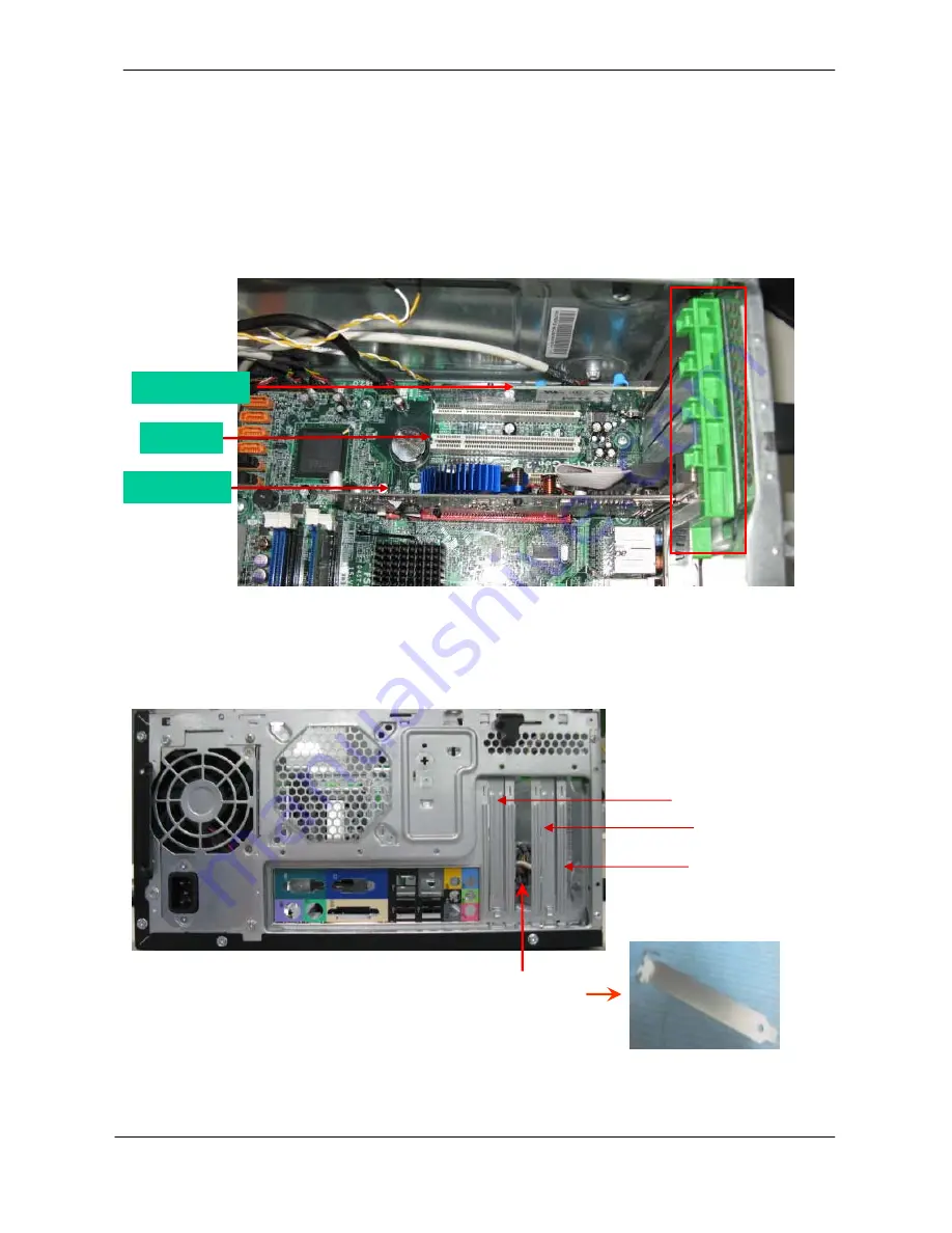
Remove Cards 


Process: 
 

1.


Release the tooless slot cover.  

 
2.


Remove VGA, TV, Modem Card. The following list references the approximate location 
 of the components. (optional by SKU) 


Notice: 

 
I.


Remove card, don’t touch any electric parts on PCB. 


Modem card 

TV card 

VGA card 

slot cover

VGA card

TV card

Modem card

Summary of Contents for Veriton M678G

Page 1: ...Veriton M678G S678G Product End of Life Disassembly Guide WAN ...

Page 2: ...rap and conductive mat for preventing electrostatic discharge Wire cutter Phillips screwdriver may require different size NOTE The screws for the different components vary in size During the disassembly process group the screws with the corresponding components to avoid mismatches when putting back the components ...

Page 3: ...fore You Begin Before proceeding with the disassembly procedure make sure that you do the following 1 Turn off the power to the system and all peripherals 2 Unplug the AC adapter and all power and signal cables from the system ...

Page 4: ...mbly Procedure This section tells you how to disassemble the system when you need to perform system service CAUTION Before you proceed make sure you have turned off the system and all peripherals connected to it ...

Page 5: ...ss 1 Put the desktop on the worktable lightly 2 Release left side cover with 2 screws then remove left side cover Remove CPU fan pipe Process 1 Release the CPU fan pipe Push the side cover lightly Screw location Screw location ...

Page 6: ...t cover 2 Remove VGA TV Modem Card The following list references the approximate location of the components optional by SKU Notice I Remove card don t touch any electric parts on PCB Modem card TV card VGA card slot cover VGA card TV card Modem card ...

Page 7: ...6 Remove HDD Data Cables Process 1 Remove master HDD data cable from M B SATA1 SATA3 2 Remove slave ODD data cable from M B SATA2 Remove slave HDD cable Remove master HDD cable SATA4 SATA3 SATA2 SATA1 ...

Page 8: ...D data power cable from master ODD Remove HDD power cable Process 1 Remove master HDD data cable from master HDD 2 Remove slave HDD data cable from slave HDD Remove master ODD Data Cable Remove master HDD Remove slave HDD Remove master ODD Power Cable ...

Page 9: ...ard reader cable from M B USB2 5 Remove audio cable from the AUDIO port on M B Notice I Recovery switch cable is next to FDD port and the black cable face to the top of chassis II Intrusion switches cable face to front bezel of chassis Remove HDD Process 1 Remove master HDD from the first HDD location 2 Remove slave HDD from the second HDD location optional by SKU ...

Page 10: ...9 Remove card reader Process 1 Remove card reader from chassis Master HDD Slave HDD ...

Page 11: ...s 1 Remove FDD digital cable just as pictures optional by SKU 2 Plug 4 pins power cord from FDD slot 3 Remove front bezel light cable from PATA power cable Remove from FDD Remove from M B FDD1 slot Remove Front bezel light cable ...

Page 12: ...11 Remove ODD Process 1 Push the lock handle release ODD 2 Remove master ODD from the location 3 Remove slave ODD from the location optional by SKU Master ODD location Slave ODD location ...

Page 13: ...12 Remove Cables Process 1 Remove M B power cable from M B ATX1 2 Remove 12 V power cable from M B JPW1 3 Remove System Fan cable from M B SYS F2 MB power cable ...

Page 14: ...13 Remove System FAN Process 1 Release four screws according to the following picture 2 Remove Sys FAN optional by SKU Release four screws 4 3 1 2 The direction of System FAN ...

Page 15: ...other board and RTC battery Process 1 Release 8 pcs screws form the corresponding hole 2 Release screws according to the following picture in turn 3 Remove the M B from chassis and remove the RTC battery form M B ...

Page 16: ...cable from M B CPU F2 2 Release screw 1 first then fixes screw 2 screw 3 screw 4 as pictures below 3 Remove cooler from the retention module Remove memory Process 1 Remove the first memory from DIMM 2 Remove the second memory from DIMM2 optional by SKU ...

Page 17: ...16 Remove CPU Process 1 Remove CPU according following the pictures Remove I O shielding Process 1 Remove I O shielding Lock the Handle ...

Reviews: