17
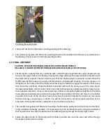
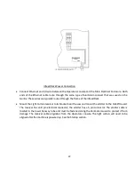
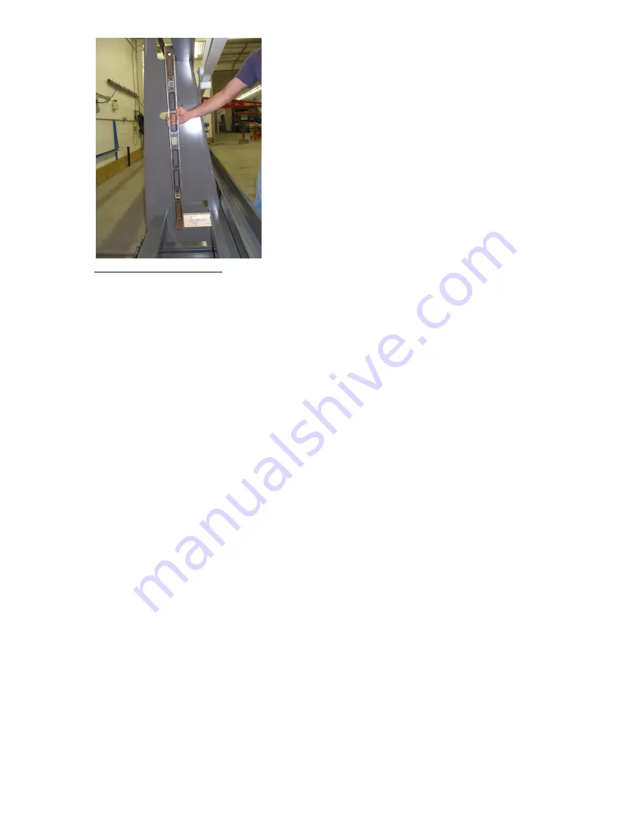
Plumbing the Guide Tubes
Locate and anchor the Operators Console guarding per the drawings.
The Lumber Cart guides and Perimeter Guarding should not be installed until the Gantry is positioned on
the Runway. This is covered in the final assembly section.
4.4 FINAL ASSEMBLY
CAUTION - SYSTEM IS INOPERABLE UNLESS THE GANTRY BRAKE SPRING IS
UN-CAGED. FOLLOW THE INSTRUCTIONS BELOW AND SEE SECTION 6.7 SAFETY BRAKE
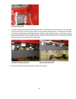
Lift the Gantry carefully from the underside with a forklift high enough that the upper wheels will just
slip over the upper track on the Runway. Raising it too high will cause the lower wheels to interfere with
the Cable Carrier support channel. Check to see that the brake plunger is properly in place. Drive the
forklift towards the Runway at an angle until the wheels are positioned properly. It may be necessary to
lift slightly on the outer end of the Gantry while lowering the forklift to engage the wheels. Check to see
that the Gantry rolls freely. Check the bottom horizontal surface of the Gantry to see if it is level. Adjust
the lower wheel bolts until it is level. Check to see that both wheels are adjusted evenly by trying to turn
them opposite directions. If one of the wheels slips (rotates) it should be tightened slightly so that both
lower wheels are loaded evenly. Remove the cage bolt from the brake chamber and store it in the holder
provided on the side of the chamber. Failure to remove the bolt will disable the brake and may cause
machine damage, serious injury or death. You will be instructed to test the proper operation of the
brake later in this section and on a daily basis in the maintenance section.
The Lumber Cart guides and Perimeter Guarding should now be positioned and anchored to the floor,
using installation drawings provided. It is imperative that the Perimeter Guard is properly installed so
that no personnel can enter the Hazardous Zone without passing through the Safety Light Curtain.
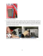
Fasten the Cable Carrier to the Gantry with the bolts provided and route the wires and airline through
the keepers located on the Gantry.
Summary of Contents for Wood Runner
Page 5: ...5 ...
Page 36: ...36 ...
Page 37: ...37 ...
Page 54: ...54 ...
Page 55: ...55 10 DETAILED PARTS IDENTIFICATION WOOD RUNNER 10 1 RUNWAY ASSEMBLY ...
Page 58: ...58 10 3 RUNWAY DRIVE ASSEMBLY ...
Page 61: ...61 10 5 GANTRY ASSEMBLY ...
Page 62: ...62 GANTRY ASSEMBLY ...
Page 64: ...64 10 6 PICKING HEAD ASSEMBLY ...
Page 65: ...65 PICKING HEAD ASSEMBLY ...
Page 68: ...68 10 7 ELECTRICAL PANEL ASSEMBLY ...
Page 70: ...70 10 8 GANTRY ENCLOSURE ASSEMBLY ...
Page 72: ...72 10 9 CONSOLE ASSEMBLY ...
Page 73: ...73 CONSOLE ASSEMBLY ...
Page 75: ...75 10 10 AIR SUPPLY ASSEMBLY ...
Page 77: ...77 10 11 GANTRY VALVE ASSEMBLY ...
Page 79: ...79 10 12 GANTRY BRAKE ASSEMBLY ...
Page 81: ...81 11 ELECTRICAL DIAGRAMS 11 1 SYSTEM OVERVIEW ...
Page 82: ...82 11 2 MAIN ENCLOSURE LOW VOLTAGE ...
Page 83: ...83 11 3 GANTRY WIRING LOW VOLTAGE ...
Page 84: ...84 11 4 I O CHART ...
Page 85: ...85 11 5 INFEED WIRING LOW VOLTAGE ...
Page 86: ...86 11 6 OPERATORS CONSOLE ...
Page 87: ...87 11 7 MAIN ENCLOSURE HIGH VOLTAGE ...
Page 88: ...88 11 8 MAIN ENCLOSURE RECEPTACLE WIRING ...
Page 89: ...89 11 9 SAFETY CIRCUIT LAYOUT ...
Page 90: ...90 11 10 SAFETY CIRCUIT DIAGRAM ...
Page 91: ...91 11 11 BRAKE SENSOR DIAGNOSIS ...
Page 92: ...92 12 PNEUMATIC DIAGRAMS 12 1 SINGLE HEAD GANTRY ...
Page 93: ...93 12 2 DOUBLE HEAD GANTRY ...
Page 94: ...94 12 3 INFEED DECK ...


