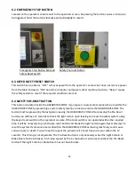
33
6.5 BRAKE BEAMS
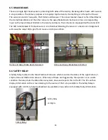
These are single light beam sensors protecting both sides of the Gantry. Breaking either beam will cause an
E-stop condition. The primary purpose is to rapidly stop the Gantry if something is in the path of travel.
The sensors consist of two parts, the Emitter and Receiver. The sensor located closest to the Infeed Deck is
the Home Brake Beam and the other sensor is the Away Brake Beam. Each sensor has a corresponding
Input on the Input/Output Module in the Gantry enclosure. These Inputs are equipped with a status LED.
The LED is illuminated if the beam sensor is not blocked. Blocking the sensor or a beam out of alignment
will cause the relay LED to go off and cause an E-stop condition.
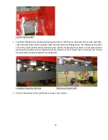
Home and Away Brake Beam Receivers
Home and Away Brake Beam Emitters
6.6 SAFETY RELAY
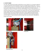
A Safety Relay located in the Main Electrical Enclosure which monitors the status of the Light Curtain, E-
stop button and Obstruction Sensors. When any of these are triggered by the operator or an unsafe
condition the relay shuts the Wood Runner system down and reports this to the PC. The PC can then
display information on the screen relating to the source of the E-stop condition. The Safety Relay is
equipped with 3 LED’s to help troubleshoot any problems. See section 6 for Safety Relay information.
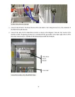
Safety Relay
Safety Relay
LED lights
Summary of Contents for Wood Runner
Page 5: ...5 ...
Page 36: ...36 ...
Page 37: ...37 ...
Page 54: ...54 ...
Page 55: ...55 10 DETAILED PARTS IDENTIFICATION WOOD RUNNER 10 1 RUNWAY ASSEMBLY ...
Page 58: ...58 10 3 RUNWAY DRIVE ASSEMBLY ...
Page 61: ...61 10 5 GANTRY ASSEMBLY ...
Page 62: ...62 GANTRY ASSEMBLY ...
Page 64: ...64 10 6 PICKING HEAD ASSEMBLY ...
Page 65: ...65 PICKING HEAD ASSEMBLY ...
Page 68: ...68 10 7 ELECTRICAL PANEL ASSEMBLY ...
Page 70: ...70 10 8 GANTRY ENCLOSURE ASSEMBLY ...
Page 72: ...72 10 9 CONSOLE ASSEMBLY ...
Page 73: ...73 CONSOLE ASSEMBLY ...
Page 75: ...75 10 10 AIR SUPPLY ASSEMBLY ...
Page 77: ...77 10 11 GANTRY VALVE ASSEMBLY ...
Page 79: ...79 10 12 GANTRY BRAKE ASSEMBLY ...
Page 81: ...81 11 ELECTRICAL DIAGRAMS 11 1 SYSTEM OVERVIEW ...
Page 82: ...82 11 2 MAIN ENCLOSURE LOW VOLTAGE ...
Page 83: ...83 11 3 GANTRY WIRING LOW VOLTAGE ...
Page 84: ...84 11 4 I O CHART ...
Page 85: ...85 11 5 INFEED WIRING LOW VOLTAGE ...
Page 86: ...86 11 6 OPERATORS CONSOLE ...
Page 87: ...87 11 7 MAIN ENCLOSURE HIGH VOLTAGE ...
Page 88: ...88 11 8 MAIN ENCLOSURE RECEPTACLE WIRING ...
Page 89: ...89 11 9 SAFETY CIRCUIT LAYOUT ...
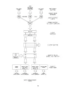
Page 90: ...90 11 10 SAFETY CIRCUIT DIAGRAM ...
Page 91: ...91 11 11 BRAKE SENSOR DIAGNOSIS ...
Page 92: ...92 12 PNEUMATIC DIAGRAMS 12 1 SINGLE HEAD GANTRY ...
Page 93: ...93 12 2 DOUBLE HEAD GANTRY ...
Page 94: ...94 12 3 INFEED DECK ...


