42
8 ADJUSTMENTS
8.1 PICKUP SCREW REPLACEMENT
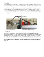
Use a ¾” wrench to hold the Screw motor arbor and remove the collet nut with a 5/8” wrench. The
screwdriver bit is free to fall out at this time. Insert the new screw into the collet nut and thread the nut
onto the arbor while aligning the screw with the screwdriver bit. Gently tighten the nut - do not over
tighten. Over tightening will damage the collet nut and shorten screw life.
Removing the collet nut
Screw replacement
8.2 DRIVE BELT TENSIONING
Park the Gantry at either end of its travel. Press the E-stop button to disable the system. Locate a very
straight 2x4x12’ board and place it on top of the top strand of belt. The board should span between two of
the belt support rollers.
Measure the sag in the belt at mid span. This is the measurement between the bottom of the 2x4 and the
top of the belt. Sag should be ¼”. Running the belt too loose will cause it to jump teeth and the Gantry will
lose its correct position. Over tightening the belt will greatly shorten belt, bearing and pulley life. An over
tightened belt will emit a whining sound during operation because the belt no longer fits the pulley tooth
spacing.
Summary of Contents for Wood Runner
Page 5: ...5 ...
Page 36: ...36 ...
Page 37: ...37 ...
Page 54: ...54 ...
Page 55: ...55 10 DETAILED PARTS IDENTIFICATION WOOD RUNNER 10 1 RUNWAY ASSEMBLY ...
Page 58: ...58 10 3 RUNWAY DRIVE ASSEMBLY ...
Page 61: ...61 10 5 GANTRY ASSEMBLY ...
Page 62: ...62 GANTRY ASSEMBLY ...
Page 64: ...64 10 6 PICKING HEAD ASSEMBLY ...
Page 65: ...65 PICKING HEAD ASSEMBLY ...
Page 68: ...68 10 7 ELECTRICAL PANEL ASSEMBLY ...
Page 70: ...70 10 8 GANTRY ENCLOSURE ASSEMBLY ...
Page 72: ...72 10 9 CONSOLE ASSEMBLY ...
Page 73: ...73 CONSOLE ASSEMBLY ...
Page 75: ...75 10 10 AIR SUPPLY ASSEMBLY ...
Page 77: ...77 10 11 GANTRY VALVE ASSEMBLY ...
Page 79: ...79 10 12 GANTRY BRAKE ASSEMBLY ...
Page 81: ...81 11 ELECTRICAL DIAGRAMS 11 1 SYSTEM OVERVIEW ...
Page 82: ...82 11 2 MAIN ENCLOSURE LOW VOLTAGE ...
Page 83: ...83 11 3 GANTRY WIRING LOW VOLTAGE ...
Page 84: ...84 11 4 I O CHART ...
Page 85: ...85 11 5 INFEED WIRING LOW VOLTAGE ...
Page 86: ...86 11 6 OPERATORS CONSOLE ...
Page 87: ...87 11 7 MAIN ENCLOSURE HIGH VOLTAGE ...
Page 88: ...88 11 8 MAIN ENCLOSURE RECEPTACLE WIRING ...
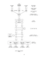
Page 89: ...89 11 9 SAFETY CIRCUIT LAYOUT ...
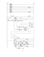
Page 90: ...90 11 10 SAFETY CIRCUIT DIAGRAM ...
Page 91: ...91 11 11 BRAKE SENSOR DIAGNOSIS ...
Page 92: ...92 12 PNEUMATIC DIAGRAMS 12 1 SINGLE HEAD GANTRY ...
Page 93: ...93 12 2 DOUBLE HEAD GANTRY ...
Page 94: ...94 12 3 INFEED DECK ...

