43
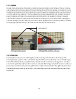
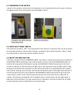
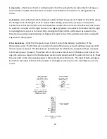
Drive Belt Tensioning – Board location
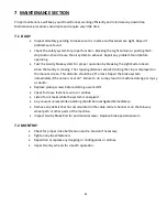
Drive Belt Tensioning – ¼” sag
8.3 DRIVE BELT ALIGNMENT
The pulleys must be properly aligned so that the belt tracks correctly on the pulleys. Poor tracking will
damage the belt or pulley flange. This procedure is done from outside the Hazardous Zone (SEE SAFETY
SECTION) while the Gantry is in Auto Cycle mode. Start the Gantry in Auto Cycle mode from the MANUAL
screen after checking that all personnel are clear of the Hazardous Zone. Observe the belt running on the
pulleys to see if it is crowding into one of the side flanges.
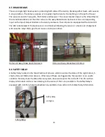
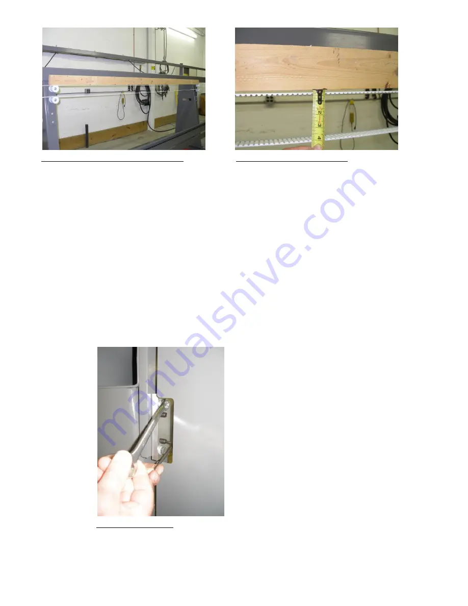
A light crowding is acceptable. Do not loosen the two bolts closest to the pulley. Adjust the alignment by
reaching through the window and loosening the two bolts closest to you ¼ turn with a 9/16” wrench.
Between these two bolts are two socket set screws. Tighten (clockwise) each of these set screws ¼ turn if
the belt is crowding the inside (closest to Runway) flange. Loosen the set screws ¼ turn if the belt is
crowding the outside flange. Retighten the 9/16” bolts and watch the belt while the Gantry makes several
cycles. Re-adjust as necessary. Repeat this procedure on the opposite end of the Runway.
Drive Belt Alignment
Summary of Contents for Wood Runner
Page 5: ...5 ...
Page 36: ...36 ...
Page 37: ...37 ...
Page 54: ...54 ...
Page 55: ...55 10 DETAILED PARTS IDENTIFICATION WOOD RUNNER 10 1 RUNWAY ASSEMBLY ...
Page 58: ...58 10 3 RUNWAY DRIVE ASSEMBLY ...
Page 61: ...61 10 5 GANTRY ASSEMBLY ...
Page 62: ...62 GANTRY ASSEMBLY ...
Page 64: ...64 10 6 PICKING HEAD ASSEMBLY ...
Page 65: ...65 PICKING HEAD ASSEMBLY ...
Page 68: ...68 10 7 ELECTRICAL PANEL ASSEMBLY ...
Page 70: ...70 10 8 GANTRY ENCLOSURE ASSEMBLY ...
Page 72: ...72 10 9 CONSOLE ASSEMBLY ...
Page 73: ...73 CONSOLE ASSEMBLY ...
Page 75: ...75 10 10 AIR SUPPLY ASSEMBLY ...
Page 77: ...77 10 11 GANTRY VALVE ASSEMBLY ...
Page 79: ...79 10 12 GANTRY BRAKE ASSEMBLY ...
Page 81: ...81 11 ELECTRICAL DIAGRAMS 11 1 SYSTEM OVERVIEW ...
Page 82: ...82 11 2 MAIN ENCLOSURE LOW VOLTAGE ...
Page 83: ...83 11 3 GANTRY WIRING LOW VOLTAGE ...
Page 84: ...84 11 4 I O CHART ...
Page 85: ...85 11 5 INFEED WIRING LOW VOLTAGE ...
Page 86: ...86 11 6 OPERATORS CONSOLE ...
Page 87: ...87 11 7 MAIN ENCLOSURE HIGH VOLTAGE ...
Page 88: ...88 11 8 MAIN ENCLOSURE RECEPTACLE WIRING ...
Page 89: ...89 11 9 SAFETY CIRCUIT LAYOUT ...
Page 90: ...90 11 10 SAFETY CIRCUIT DIAGRAM ...
Page 91: ...91 11 11 BRAKE SENSOR DIAGNOSIS ...
Page 92: ...92 12 PNEUMATIC DIAGRAMS 12 1 SINGLE HEAD GANTRY ...
Page 93: ...93 12 2 DOUBLE HEAD GANTRY ...
Page 94: ...94 12 3 INFEED DECK ...

