15.
This
product should be operated only from the type of
power source indicated on the marking label. If you are not
sure of the type of power supply to your home, consult your
product dealer or local power company. For products
intended to operate from battery power, or other sources,
refer to the operating instructions.
8.
Do
not install near any heat sources such as radiators, heat
register, stoves, or other apparatus (including amplifiers)
that produce heat.
9.
Do
not defeat the safety purpose of the polarized or
grounding-type plug. A polarized plug has two blades with
one wider than the other. A grounding type plug has two
blades and third grounding prong. The wide blade or the
third prong are provided for your safety. If the provided plug
does not fit into your outlet, consult an electrician for
replacement of the obsolete outlet.
10.
Protect
the power cord from being walked on or pinched
,
particularly at plugs, convenience receptacles, and the
point where they exit from the apparatus.
11.
Only
use attachments and accessories specified by the
manufacturer.
12.
Use
only with the cart, stand, tripod,
bracket, or table specified by the
manufacturer, or sold with the apparatus.
When a cart is used, use caution when
moving the cart.
13.
Unplug
this apparatus during lightning storms or if
unused for a
long period of time.
14. Refer all servicing to qualified service personnel.
Servicing is required when the apparatus has been
damaged in any way, such as when
the
power-supply
cord or plug is damaged, liquid has been spilled or objects
have fallen into the apparatus, the apparatus has been
exposed to rain or moisture, does not operate normally, or
20.
Replacement Parts
When replacement parts are required, be sure the service
technician has used replacement parts specified by the
manufacturer or have the same characteristics as the
original part. Unauthorized substitutions may result in fire,
electric shock, or other hazards.
21.
Safety Check
Upon completion of any service or repairs to this product,
ask the service technician to perform safety checks to
determine that the product is in proper operating
condition.
22.
Wall or Ceiling Mounting
The product should be mounted to a wall or ceiling only as
recommended by the manufacturer. Any mounting of the
product should follow the manufacturer instructions, and
should use a mounting accessory recommended by the
manufacturer.
23.
Wet location marking
Apparatus shall not be exposed to dripping or splashing
and no objects filled with liquids, such as vases, shall be
placed on the apparatus.
1.
Read
These Instructions.
2.
Keep
These Instructions.
3.
Heed
All Warnings.
4.
Follow
All Instructions.
5.
Do
not use this product near water.
6.
Clean
only with a
dry cloth.
7.
Do
not block any ventilation openings.
Important Safety instructions
16.
Protective Attachment Plug
The product is equipped with an attachment plug having
overload protection. This is a safety feature. See
Instruction Manual for replacement or resetting of
the
protective device. If replacement of the plug is required, be
sure the service technician has used a replacement plug
specified by the manufacturer that has the same overload
protection as the original plug.
17.
Power Lines
An outside antenna system should not be located in the
vicinity of overhead power lines or other electric light or
power circuits, or where it can fall into such power lines or
circuits. When installing an outside antenna system,
extreme care should be taken to keep from touching such
power lines or circuits as contact with them might be fatal.
19.
Object and Liquid Entry
Never push objects of any kind into this product through
openings as they may touch dangerous voltage points or
short-out parts that could result in a fire or electric shock.
Never spill liquid of any kind on the product.
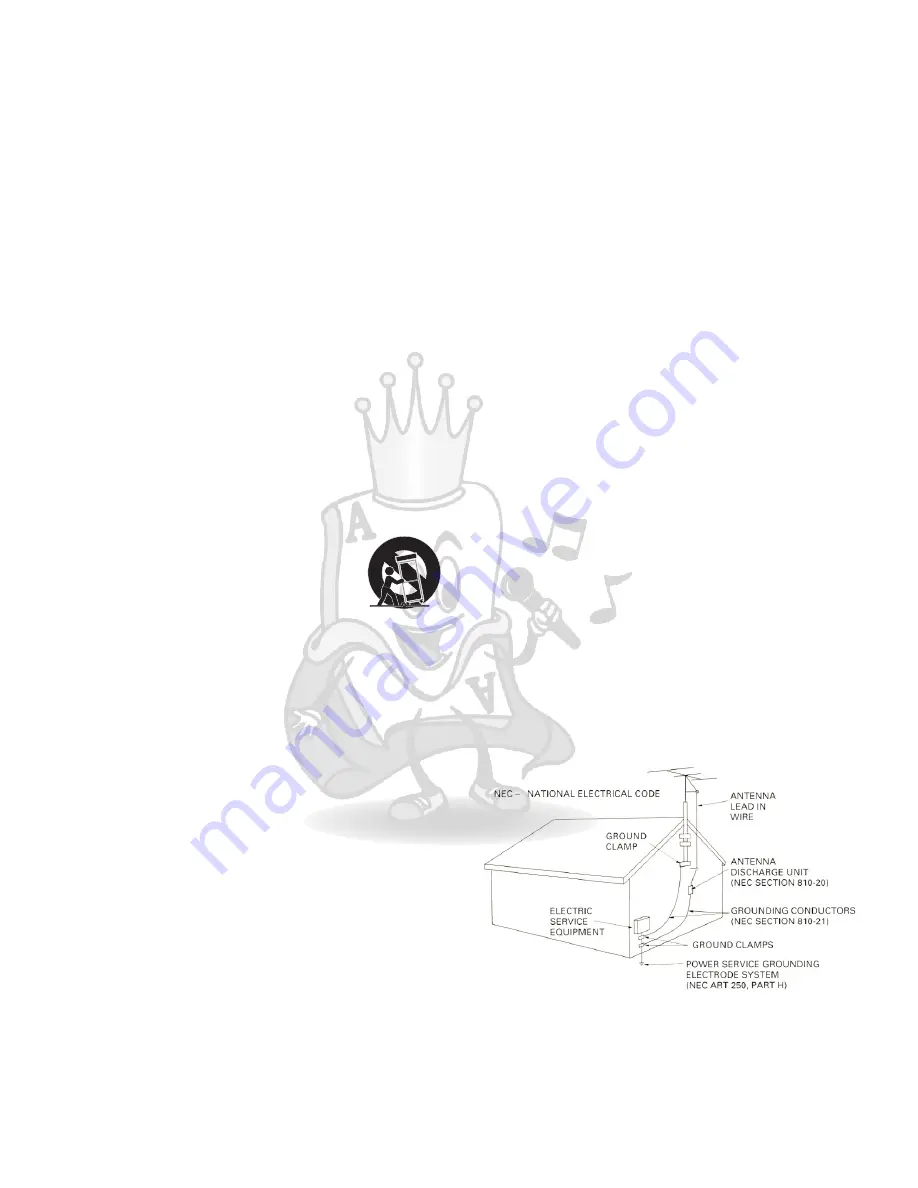
24.
Outdoor Antenna Grounding
If an outside antenna or cable system is connected to the
product, be sure the antenna or cable system is grounded
so as to provide some protection against voltage surges
and built-up static charges. Article 810 of the National
Electrical Code, ANSI/NFPA 70, provides information with
regard to proper grounding of the mast and supporting
structure, grounding of the lead-in wire to an antenna
discharge unit, size of grounding conductors, location of
antenna discharge unit, connection to grounding
electrodes, and requirements for the grounding electrode.
See figure below.
25.
Servicing
If your product is not operating correctly or exhibits a
marked change in performance and you are unable to
restore normal operation by following the detailed
procedure in its operating instructions, do not attempt to
service it yourself as operating instructions, do not attempt
to service it yourself as opening or removing covers may
expose you to dangerous voltage or other hazards. Refer
all servicing to qualified service personal.
18.
Overloading
Do not overload wall outlets, extension cords, or integral
convenience receptacles as this can result in a risk of fire
or electric shock.
3


