background image

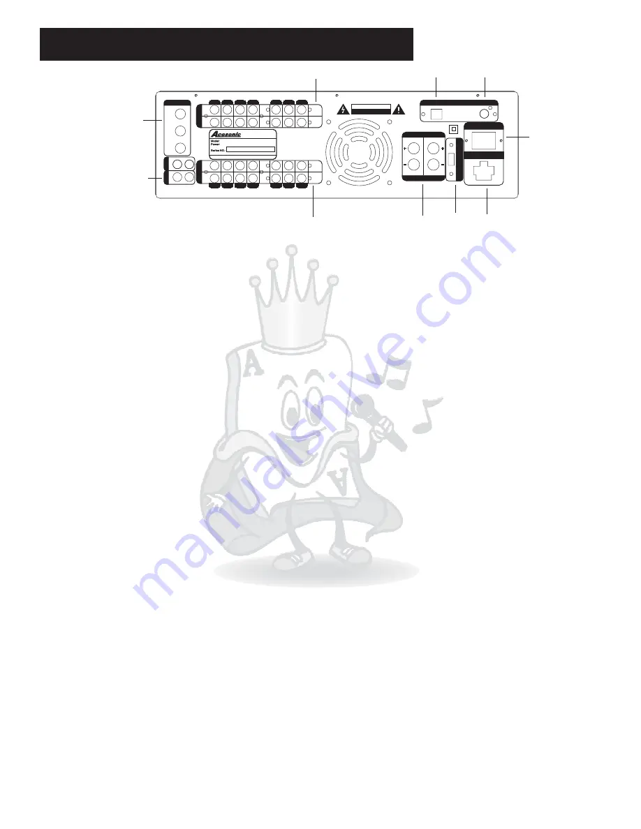
Rear Panel Function and Operation

INPUT

MIC 1

MIC 1

MIC 2

MIC 2

MIC 3

MIC 3

MIC INPUT

MIC INPUT

OUT

IN

OUT

IN

VIDEO

ML

MR

S-VIDEO

R

G

B

VIDEO

ML

MR

S-VIDEO

R

G

B

OUTPUT

BGM

DVD

DO NOT REMOVE LOOP

DO NOT REMOVE LOOP

CITY OF INDUSTRY, CA, USA

CITY OF INDUSTRY, CA, USA

AM-828

AC115V/AC230V(50-60Hz)

Http://www.acesonic.com

MIXING AMPLIFIER

MIXING AMPLIFIER

AC

115

/

230V

SELECT

AC

115

/

230V

SELECT

EQ

L
EQ

L

EQ

R
EQ

R

SPEAKER SYSTEM

SPEAKER SYSTEM

SPEAKER SYSTEM

SPEAKER SYSTEM

R

R

L

L

OUTLET UNSWITCHED

AC 115/230V 60/50Hz 250W MAX

OUTLET UNSWITCHED

AC 115/230V 60/50Hz 250W MAX

AC 115 / 230V

AC 115 / 230V

60 / 50 Hz 500W MAX

60 / 50 Hz 500W MAX

PC

CONNECTION

PC

CONNECTION

VIDEO INPUT

VIDEO INPUT

CAUTION

RISK OF ELECTRIC SHOCK

DO NOT OPEN

RISK OF ELECTRIC SHOCK

DO NOT OPEN

1

4

3

2

10

9

8

7

5

1.MIC INPUT jacks (1, 2, 3)-
2.AUDIO/VIDEO OUTPUT

a.MR-

b.ML-
c.VIDEO -
d.S-VIDEO -

e.RGB-

3.AUDIO/VIDEO INPUT jacks (BGM, DVD) -

a.MR-

b.ML-

c.VIDEO-
d.S-VIDEO-

e.RGB-

4.EQ L/R INPUT and OUTPUT jacks -

5.PC CONNECTION -
6.VIDEO INPUT-
7.AC inlet -
8.AC outlet -
9.AC 115/230V SELECT-

10.SPEAKER SYSTEM

1/4 inch inputs for microphones.

jacks (2 sets) Each row consists of a complete set of AUDIO

LEFT, AUDIO RIGHT, VIDEO, S-VIDEO, and RGB VIDEO outputs:

AUDIO RIGHT RCA output. Connect to the audio right input on an external

component.

AUDIO LEFT RCA output. Connect to the audio left input on an external component.

VIDEO RCA output. Connect to the video input on an external component.

S-VIDEO (Y/C) output. Connect to the S-VIDEO input on an external

component.

RED, GREEN, BLUE component video RCA outputs. Connect to the red, green

and blue component video inputs, respectively, on an external component.

Each row consists of a complete set of AUDIO

LEFT, AUDIO RIGHT, VIDEO, S-VIDEO, and RGB VIDEO inputs. The top row is designated
as the BGM input, and the bottom row as the DVD input:

AUDIO RIGHT RCA input. Connect to the audio right output from an external

component.

AUDIO LEFT RCA input. Connect to the audio left output from an external

component.

VIDEO RCA input. Connect to the video output from an external component.

S-VIDEO (Y/C) input. Connect to an S-VIDEO output from an external

component.

RED, GREEN, BLUE component video RCA inputs. Connect to the red, green and

blue component video outputs, respectively, from an external component.

For external equalizer connection. Utilize to send

and return AM-828 input signal to and from an external equalizer for further signal
processing. (Please see connection diagram on page 8 for proper configuration)

USB connection used to interface with computer-based devices.

additional VIDEO RCA input.

Male inlet for alternate current adapter.

Female outlet for alternate current adapter.

Supply voltage selection switch. Push the switch down for 115V,

and up for 230V. (Note: different regions of the world use different voltage strength. Please
check to make sure the correct voltage is selected for your area.)

- Provides audio output to stereo external speakers. Designed to

be used with bare speaker wire as well as banana connectors. The LEFT and RIGHT
outputs each consist of a positive (+, red) and negative (-, black) signal that correspond
with the inputs on each speaker. (Please see connection diagram on page 8 for proper
configuration)

-

6

7

Summary of Contents for AM-828

Page 1: ...db L R MUTE BBE L STEREO R VOCAL PARTNER VOCAL PARTNER VOCAL CANCEL VOCAL CANCEL DVD 4 5 6 DVD AUX USB BGM AUTO INPUT SELECTOR INPUT SELECTOR SOUND MODE SOUND MODE POWER KEY CONTROL KEY CONTROL BALAN...

Page 2: ...TS The exclamation point within an equilateral triangle is intended to alert the user to the presence of important operating and maintenance servicing instructions in the literature accompanying the a...

Page 3: ...s filled with liquids such as vases shall be placed on the apparatus Wet location marking 23 Apparatus shall not be exposed to dripping or splashing and no objects filled with liquids such as vases sh...

Page 4: ...nnections Diagrams 9 10 General Operation 11 12 Troubleshooting 13 Specifications 14 Warranty Information 15 16 Front Panel Functions and Operation 5 6 Acesonic AM 828 For easy reference names of all...

Page 5: ...ls Please note the microphone inputs will NOT be affected Adjusts the high frequency setting for DVD AUX USB BGM inputs Turn counter clockwise to decrease and clockwise to increase Adjusts the low fre...

Page 6: ...output signal to left channel only Switches output signal to both left and right channels default Switches output signal to right channel only Select this for vocal removal on Multiplex song sources T...

Page 7: ...ent RED GREEN BLUE component video RCA outputs Connect to the red green and blue component video inputs respectively on an external component Each row consists of a complete set of AUDIO LEFT AUDIO RI...

Page 8: ...tion to automatic mode Mutes all output signal from the selected input source Selects the external source connected to the DVD INPUT Selects the external source connected to the AUX INPUT Selects the...

Page 9: ...VE LOOP DO NOT REMOVE LOOP CITY OF INDUSTRY CA USA CITY OF INDUSTRY CA USA AM 828 AC115V AC230V 50 60Hz Http www acesonic com MIXING AMPLIFIER MIXING AMPLIFIER AC 115 230V SELECT AC 115 230V SELECT EQ...

Page 10: ...INDUSTRY CA USA AM 828 AC115V AC230V 50 60Hz Http www acesonic com MIXING AMPLIFIER MIXING AMPLIFIER AC 115 230V SELECT AC 115 230V SELECT EQ L EQ L EQ R EQ R SPEAKER SYSTEM SPEAKER SYSTEM SPEAKER SY...

Page 11: ...the front panel selects the source connected to PC CONNECTION on the rear panel selects the source connected to BGM INPUT on the rear panel Press to set the input source selection to automatic mode In...

Page 12: ...nter clockwise to decrease intensity and clockwise to increase intensity Adjusts the ECHO decay time number of ECHO of the echo effect for the microphone channels Turn counter clockwise to decrease de...

Page 13: ...audio source units Try using another set of cables cords Make sure to turn POWER OFF before reconnecting cables No audio can be heard audio signal meter DOES NOT show signal No microphone signal can...

Page 14: ...0dB 10Khz Bass 10dB 100hz Music EQ characteristics Treble 10dB 10Khz Bass 10dB 100hz Key Control Range 6 half tones Speaker Wattage Impedance 6 Ohm 8 Ohm Supply Voltage AC 110V 120V or AC 220V 240V sw...

Page 15: ...ard in a safe place for future reference WARRANTY SERVICE MUST BE PERFORMED ONLY BY AN AUTHORIZED ACESONIC SERVICE FACILITY LOCATED IN THE COUNTRY WHERE THE UNIT WAS PURCHASED OR AT THE ACESONIC HEADQ...

Page 16: ...R PROPERTY MAY RESULT FROM THE OF THE PRODUCT HOWEVER EVEN IF ACESONIC HAS BEEN ADVISED OF THIS POSSIBILITY THIS LIMITED WARRANTY DOES NOT COVER ANY SUCH CONSEQUENTIAL OR INCIDENTAL DAMAGES SOME STATE...

Reviews: