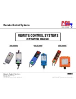
Remote Control Systems
PAGE: 2
200, 400, and 500 Series
Remotes-0214
2721 NE 4th Ave Pompano FL 33064 | (954) 367-6116
Visit WWW.ACIHOIST.COM for the most current information
TABLE OF CONTENTS
1.0 WARRANTY .............................................................................................................................................................. 4
2.0 SAFETY PRECAUTIONS ........................................................................................................................................... 5
2.1 Safety Alert Symbols ...................................................................................................................................... 5
2.2 Operating Precautions ................................................................................................................................... 6
2.2.1 Attention ......................................................................................................................................... 6
2.2.2 Precautions (500 Series) ................................................................................................................. 6
2.2.3 Emergency Procedures (500 Series) ............................................................................................... 6
3.0 GENERAL OPERATION (500 SERIES) ..................................................................................................................... 7
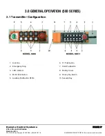
3.1 Transmitter Configuration .............................................................................................................................. 7
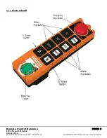
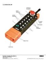
3.1.1 Model 5008AB ................................................................................................................................ 8
3.1.2 Model 50011AB .............................................................................................................................. 9
3.2 General Operation ........................................................................................................................................10
3.3 Special Functions Operation .........................................................................................................................10
3.3.1 Power-On Operations ...................................................................................................................10
3.3.2 Acceleration Operation ..................................................................................................................11
3.3.3 Inching Operation ..........................................................................................................................11
4.0 FUNCTION SETTINGS (DEFINED BY CUSTOMER) .............................................................................................. 12
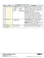
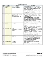
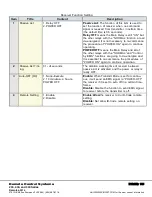
4.1 Pushbutton Function Setting: ........................................................................................................................12
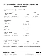
5.0 CORRESPONDENCE BETWEEN PUSHBUTTON AND RELAY OUTPUT (500 SERIES) ....................................... 16
6.0 ID-CODE REMOTE SETTING (500 SERIES) .......................................................................................................... 18
7.0 RECEIVER VOLTAGE SELECTION (500 SERIES) ................................................................................................. 20
7.1 Switch the plug to choose voltage ................................................................................................................20
8.0 BOARD LAYOUTS .................................................................................................................................................. 21
8.1 Transmitter PC Board Layout (200 & 400 Series) ..........................................................................................21
8.2 Receiver PC Board Layouts (200 & 400 Series) .............................................................................................22
8.3 Independent COM Line .................................................................................................................................25
9.0 FREQUENCY CHANGE (200, 400, & 500 SERIES) ................................................................................................ 26
9.1 Procedures ...................................................................................................................................................26
9.2 VHF Band Conversion Table .........................................................................................................................28
9.3 UHF Band Conversion Table ........................................................................................................................29
9.4 Changing RO/START N.O. (normally open) INTO N.C. (normally closed) ......................................................30
10.0 TROUBLESHOOTING ........................................................................................................................................... 31
11.0 WIRING DIAGRAMS ............................................................................................................................................. 32
12.0 DIMENSIONS & SPECIFICATIONS ...................................................................................................................... 34
12.1 Dimensions .................................................................................................................................................34
12.1.1 500 Series: Model 5008 ...............................................................................................................34
12.1.2 500 Series: Model 50011 .............................................................................................................35

