The antenna may be mounted internally in composite construction, and tubular fabric
covered aircraft, as long as the fabric or composite material is of a non conductive nature.
The antenna must be mounted externally, on airframes of metallic construction. The
antenna should be mounted as close to the ELT transmitter as practical. The coaxial cable
connecting the antenna to the ELT transmitter, should not run in close proximity to comm
radio coaxial cables, and should avoid crossing aircraft production breaks. (i.e. Riveted
fuselage sections) The antenna must be mounted within 30 degrees of vertical, when the
aircraft is in normal flight attitude. The installed antenna must be able to withstand a static
load of 100 (one hundred) times it’s weight (13 lbs.) applied to the base of the antenna,
along the longitudinal axis of the aircraft. The antenna should be mounted a minimum dis-
tance of three feet (1 meter) from any vertically polarized communication antennas. (i.e.
Antennas radiating in the 118-137 MHz band.)
MODEL E-04.8 WHIP ANTENNA
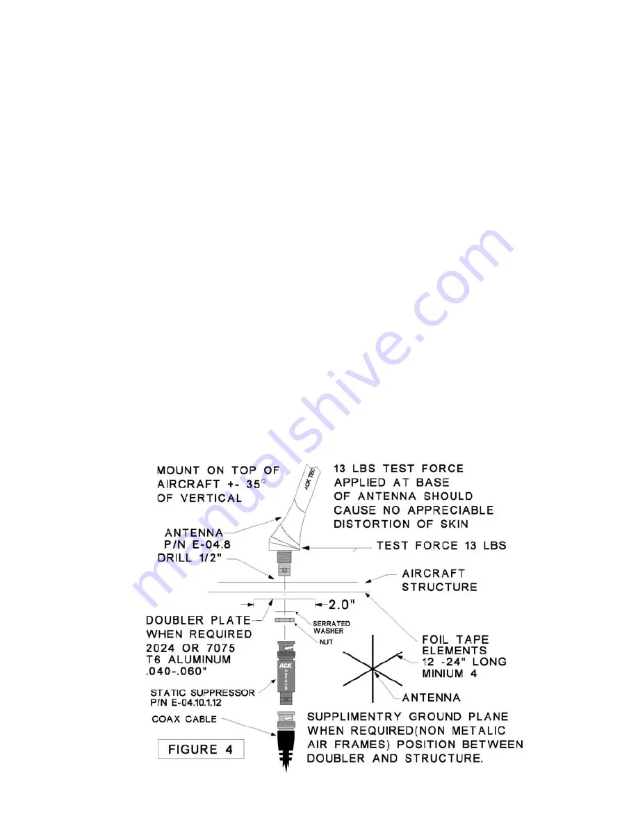
1.) Drill a ½" (13mm) diameter hole in the aircraft at the antenna mounting location (Fig. 4)
2.) Install the antenna, and determine if the antenna meets the static load requirements. If
not, a doubler plate should be fabricated.
3.) If the antenna is being mounted on a non conductive portion of the airframe, a
supplementary ground plane must be installed. The supplemental ground plane must have
a minimum diameter of 24" however 48” will provide maximum power at 121.5 MHz and is
recommended. The ground plane must be centered around the base of the antenna. This
may be fabricated out of copper, or aluminum tape. The tape should be cut into six ele-
ments 12" long, and the tape elements should be evenly spaced, radiating in a circular
pattern from the base mounting point of the antenna. (Fig. 4) Make sure all elements are
electrically bonded to the base of the antenna. The tape may follow the contour of the fuse-
lage. The metallic airframe of fabric covered aircraft may be used as the ground plane.
When installing the antenna, make sure the base of the antenna is electrically bonded to
the tubing frame. A static suppressor is supplied install as shown in (Fig 4)
4.) Assemble the antenna as shown in figure 4. Make sure the rubber washer that forms a
moisture seal between the antenna base, and aircraft structure, is in place before installing
the antenna. Also make sure the serrated locking washer is in place. If the aircraft skin at
the mounting point is less than .060” thick when installing the P/N E-04.8 whip antenna, a
2” diameter doubler plate must be fabricated using .040” thick 2024, or 7075 T6 aluminum.
4
ALL WIRE SUPPLIED WITH THE ELT MEETS THE REQUIREMENTS OF FAR 23.1359 AND
FAR 23.853 AND MAY BE INSTALLED IN ANY PART 23 CERTIFIED AIRCRAFT.
WARNING: Do not
install static suppressor
directly to ELT BNC
terminal.


