1Ø
Single Phase 2 Wire Systems (using inputs ‘A1’, ‘L1’ and ‘N’)
Simply place the current sensor A1 around the current carrying conductor, then
connect ‘L1’ to System Live/Hot and connect ‘N’ to System Neutral. We would not
recommend connecting the Neutral (N) to anything other than System Neutral. We
do not recommend connecting this input to an external System Ground (G) or Earth
(E) as the floating voltage on the Neutral (internal Star-point) could trip sensitive
Earth Fault or Earth Leakage protection equipment.
When logging voltage on single
phase systems, we recommend you connect all 3 input phases (L1, L2 & L3) to live and N
to system neutral, this ensures the logger gets sufficient power and does not revert to
battery power.
1Ø Single Phase 3 Wire Systems (
inputs ‘A1’, ‘A2’, ‘L1’, ‘N’ and ‘L2’)
Place the current sensor ‘A1’ around the current carrying conductor, place A2
around the Ground/Earth conductor. Now connect (IN THIS ORDER) ‘N’ to System
Neutral, then ‘L1’ to System Live/Hot.
NOW, before connecting ‘L2’ to System
Ground/Earth use a voltmeter to check that there is no voltage on logger input ‘L2’
which, when connected to System Ground/Earth could draw a fault current through
System Ground/Earth and trip the system! Typically with ‘L1’ and ‘N’ connected
there is around 0.5Vac on ‘L2’, which is normally too low to trip an Earth Fault
Relay! HOWEVER please do check your setting prior to connection.
Finally connect
‘L2’ to System Ground/Earth last. To disconnect, remove the System Ground/Earth
connection to ‘L2’ first, then the other inputs to L1 and N after.
When logging voltage
on single phase systems, we recommend you connect all 3 input phases (L1, L2 & L3) to
live and N to system neutral, this ensures the logger gets sufficient power and does not
revert to battery power.
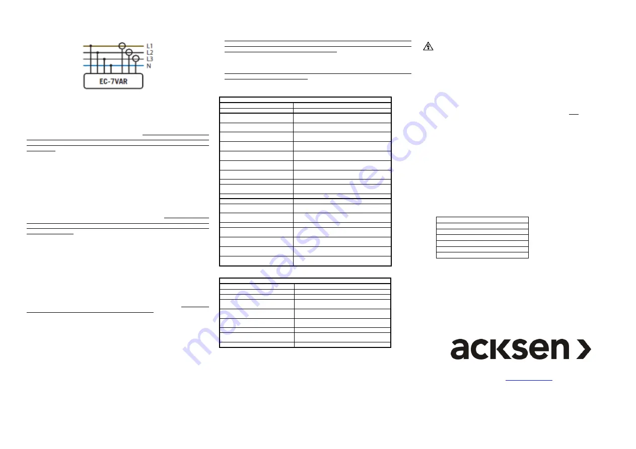
3Ø Phase Wye/Star and 3 Phase Delta (inputs A1 - A3, L1 - L3 & N)
This recorder has an internal star-point, which is internally connected to the Neutral
(N) input. For unbalanced three phase voltage inputs it is likely that the star-point
will have a ‘floating’ voltage with respect to an external ground. We would therefore
NOT recommend connecting the Neutral (N) input to an external system Ground (G)
or Earth (E) as the floating voltage on the Neutral (internal Star-point) could trip
sensitive Earth Fault or Earth Leakage protection equipment;
connect Neutral (N)
input to System Neutral only!
3Ø Phase Wye/Star Current Only (inputs A1 - A3)
This recorder can be used for recording current only, however it should be noted
that running on battery only (as there are no voltage connections) will severely
reduce battery life and limit the amount of recording time. Please also not that the
green recording LED will not flash as this only lights when the logger is powered
from external voltage supply, this is to conserve battery life.
It is strongly
recommended that you connect one voltage phase input L1 and N Neutral (N) to
supply voltage to the logger, which prolongs battery life.
Power Factor (PF or Cos
φ) is measure between the voltage waveform on L1 and
the current waveform on A1. When logging has commenced, the logger will display
a rough indication of the PF value being measured:-
Both LEDs on = PF between 0.9 leading and 0.9 lagging (~ unity).
Left LED on = PF < 0.9 leading.
Right LED on = PF < 0.9 lagging.
No LEDs on = insufficient data, current too low or too noisy (harmonics).
Power Factor measurement accuracy is affected by the levels of voltage and current
on the inputs L1 and A1, best results are achieved when the input levels on each are
greater than 30% of scale for both L1 and A1 inputs.
Correct Rogowski Coil orientation.
Each Rogowski Coil is marked with an arrow on the black plastic coupling, this arrow
must point in the direction of the load.
Technical Specifications
V
OLTAGE
C
HANNELS
TECHNICAL SPECIFICATIONS
(subject to change without notice)
Measurement range (Vrms)
600Vrms (Ph
– Ph)
or 0V to 348Vrms (Ph
– N)
Maximum channel input voltage
600Vrms (Ph
– Ph), 348Vrms (Ph – N), 700Vpeak.
Inputs (non-isolated inputs)
Three phase inputs (
L1, L2 & L3
) & Neutral (
N
),
Non-isolated input channels!
Input socket types
4mm shrouded ‘banana’ plugs & sockets, each with
insulated crocodile clip.
Measurement accuracy
±1% of reading
(10 bit) within 90Vac - 450Vrms (ph
– ph); else ±3%. (50/60Hz ±2%)
Vmin & Vmax meas time resolution
Always one cycle (50/60 Hz), independent of
selected averaging period.
Sampling frequency
16 samples per cycle
800Hz @ 50Hz
or
960Hz @
60Hz
Data recorded
Average voltage, max & min voltage-cycle-value
during the averaging period
Memory capacity
192kB able to record 32,000 Voltage levels per
phase.
Memory type
Non-volatile SEEPROM
Memory - averaging period & duration
2 sec to 60 mins (1sec. avg gives 2 hrs of logging,
60min. avg gives 300 days of logging)
Real-time clock accuracy
Greater than 0.001%
Input Lead Length
Metric
1.0 metres
Imperial
3’ 6” (3 feet, 6 inches)
Battery life (while plugged in)
Unlimited - mains powered & battery backup (9,000
hours, 1 year while unpowered).
Battery Type
Unit contains
three
9V Alkaline batteries (E-Block,
PP3, 1604A).
Communications Interface type
USB.
Electrosoft Software
Windows (9x, 2K, ME, NT, XP, Vista, Windows 7);
1024 x768 min resolution
Environmental (temp & sealing)
-10C to +40C
or
+14°F to +104°F
–
Indoor or
protected environment only!
Dimensions & Weight
Metric
250 x 160 x 160mm &
1kg
Imperial
-
10” x 6” x 6” & 2lb
Standards
Recording - EN50160: 1994 - CAT III, maximum input voltage
500Vac.
Technical Specifications
C
URRENT
C
HANNELS
TECHNICAL SPECIFICATIONS
(subject to change without notice)
Current Range
400A is ~4A to400A, model3kA is ~20 to 3kA
Current Measurement Accuracy
2% of reading 100 to 500A, otherwise 10%
Sampling frequency
16 samples per cycle
800Hz @ 50Hz
or
960Hz @
60Hz
Data recorded
Average current, max & min current-cycle-value
during the averaging period
Memory capacity
192kB able to record 32,000 current levels per
channel.
Memory type
Non-volatile SEEPROM
Memory - averaging period &
duration
1 sec to 60 mins (1sec. avg gives 2 hrs of logging,
60min. avg gives 300 days of logging)
Power Factor (
Cos φ)
3% to 0.5 lead/lag & 10% from 0.5 to 0.3 lead/lag.
Calibration
Each unit is individually calibrated during testing.
Battery life (logging while connected)
Unlimited - mains powered and battery back up.
Battery life (logging while unpowered)
The 9V Alkaline batteries should last for at least 30 hours.
Caution
The batteries used in this device may present a risk of fire or chemical burn if mistreated. Do not
recharge, disassemble, heat above 100°C or incinerate. Replace with a 9V Lithium or Alkaline
battery IEC Type 6-F22 (PP3, MN1604). Use of another battery may present a risk of fire or
explosion. Dispose of used batteries promptly. Check for signs of battery (electrolyte) leakage. If
leakage has occurred, the PCB must be cleaned in an approved manner by a competent (trained)
person. Keep away from children.
Maintenance
Prior to each use of the logger check the Electrocorder casing for signs of damage (cracks,
broken or loose parts) or misuse. Check the leads for any signs of damage, ensure the outer
insulation later is not broken. If the unit is damaged in any way it must
NOT
be used and should
be returned to the supplier. The unit must not be used for any other purpose than for that
recommended by the manufacturer. The unit must not be submerged in any liquid. When
replacing batteries on IP65 models, you may have to loosen the outer nut on the cable-gland on
the voltage leads, to allow the leads to move, so the rear of the case can be opened. Tighten
them again when finished replacing the batteries.
Cleaning
Wipe the outside of the case with a clean cloth damped with IPA (Isopropyl Alcohol).
Warranty
All Acksen products carry a minimum 1 year back to base warranty covering manufacturing
defects and component failures. The device contains no user-serviceable parts
and as such
should only be repaired by skilled and authorised personnel. Failure to comply could result in
unsafe operation and should not be attempted under any circumstances. Contact below for a list
of approved service agents.
Note:
Any unauthorised repair or adjustment will automatically render
the warranty invalid.
Repair and spare parts
Acksen Ltd.
28 Station Road
Whiteabbey
Newtownabbey
Co. Antrim BT37 0AW
United Kingdom
Or an approved repair company.
Returning a product for repair
If returning a product to the manufacturer for repair, it should be sent freight pre-paid to the
appropriate address. A copy of the Invoice and of the packing note should be sent simultaneously
by airmail to expedite clearance through Customs. A repair estimate showing freight return and
other charges will be submitted to the sender, if required, before work on the device commences.
WEEE
For EU customers Acksen Ltd offer a product take-back service. For customers within the
European Union (only) and products manufactured or sold by us; when those products reach the
end of their life, simply send them back to us at your expense, we will dispose of them according
to the relevant legislation. WEEE Reg. No. WEE/DD2117VU.
Part No: EC-7VAR-UI-En.PDF
Web:
Email: sales@acksen.com


