background image


-

3


SOFTWARE CONFIGURATION


4. 

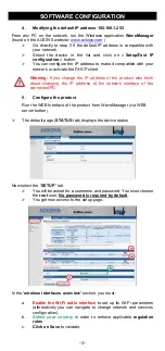
Modifying the default IP address 192.168.1.253 

From  any  PC  on  the  network,  run  the  Windows  application 

WaveManager 

(found on the ACKSYS website

www.acksys.com

 ) 


Go  directly  to  step  5  if  the  default  IP  address  is  compatible  with 
your network. 


Select  the  device  in  the  list  and  click  on  «

 Setup/Fast  IP 

configuration

 » button. 


You can configure the IP address to make it compatible with your 
network or activate the DHCP client. 


Warning:

  If  you  change  the  IP  address  of  the  product  also  think 

about  changing  the  IP  address  of  the  network  interface  of  the 
connected PC. 


5. 

Configure the product 

Run the


WEB Interface of the product from WaveManager (via WEB 

server button) 


The default page (

STATUS

 tab) displays the device status


Now select the “

SETUP

” tab. 


You will be asked for a username and password. You must choose 
the 

root

 user. 

No password is required by default


You get now access to the setup page. 


In the “

wireless interfaces overview

” section, you must: 


a. 

Enable  the  Wi-Fi  radio  interface

  to  set  up  its  Wi-Fi  parameters 

(alternatively  you  can  navigate  to  change  network  and  services 
configuration).  

b. 

Select  your  country

  in  order  to  enforce  applicable 

regulation 

rules


c. 

Click on Save 

to validate. 

Summary of Contents for AirBox Series

Page 1: ...uatre V3 ou cinq antennes WiFi V1 V2 La présente documentation Avant de continuer assurez vous d avoir les dernières mises à jour des documentations et du firmware du produit en consultant notre site web www acksys fr Consultez le manuel WaveOS user guide Vous aurez besoin de un PC Windows pour installer le logiciel ACKSYS WaveManager un navigateur internet récent un smartphone Android pour instal...

Page 2: ...ions Alimentation et Connecteur pour les caractéristiques et le câblage de l alimentation Le produit n a pas de bouton Marche Arrêt il démarre automatiquement dès la mise sous tension Vérifiez les voyants PWR1 et PWR2 PWR1 s allume si l alimentation 1 ou PoE est présente PWR2 s allume si l alimentation 2 est présente La LED Diag reste allumée en rouge environ 1 minute jusqu à ce que le produit soi...

Page 3: ... à modifier l adresse IP de l interface réseau du PC connecté 5 Configurer le produit Pour poursuivre la configuration du produit il suffit d accéder au serveur WEB du produit via le bouton Serveur WEB Par défaut la page STATUS du produit s affiche Sélectionnez l onglet SETUP Pour être autorisé à modifier la configuration vous devez choisir l utilisateur root Par défaut il n y a pas de mot de pass...

Page 4: ...pourrez alors modifier Le mode de fonctionnement Point d accès Client bridge Mesh Les paramètres Wi Fi Mode 802 11 canaux Prendre en compte la législation en vigueur dans votre pays SSID Les paramètres de sécurité WEP WPA SSID diffusé ou pas Vous trouverez un descriptif complet sur ces modes de fonctionnement dans le manuel d utilisation du firmware WaveOS Ne pas oublier d enregistrer vos paramètr...

Page 5: ...é d un adaptateur sans fil Paramétrez la connexion sans fil du PC2 selon les paramètres d usine fixés dans le point d accès Méthode pour essayer le produit en rôle client bridge Avec deux produits ACKSYS et un second ordinateur équipé d une prise LAN filaire Paramétrez les adresses IP des équipements comme indiqué ci dessus et configurez le produit connecté à PC2 pour le rôle Client infrastructure...

Page 6: ...nt et AP Vérifiez les conditions radio distance entre équipements position et orientation des antennes interférences et obstacles aux ondes radio Essayez temporairement sans les paramètres de sécurité Testez comme indiqué dans la section Mise en œuvre rapide Essayez un autre canal radio WaveManager ne trouve pas le produit WaveManager scanne seulement le réseau local Vérifiez que WaveManager n est...

Page 7: ...ste 2 possibilités pour relier le produit à la terre Utiliser le bornier d alimentation en face avant Utiliser la languette de terre 0 81x6 35 mm présente sur la face latérale droite Nous recommandons pour une mise à la terre efficace cette dernière méthode Pour ce faire réaliser un câble à partir d une tresse métallique sertie à une cosse femelle non fournies ...

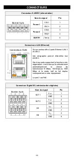
Page 8: ...igraphie permet d identifier leur position Ces deux ports supportent la fonction auto négociation c est à dire qu ils sélectionnent automatiquement la vitesse de transmission 10 Mbps 100 Mbps ou 1000 Mbps et le mode half ou full duplex correspondant à votre équipement Le port 2 est PoE Connecteur Digital I O entrées sorties digitales Bornier 8 pts Nom du signal Pin OUT1 Vout1 1 GND 5 OUT2 Vout2 2 ...

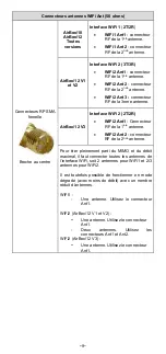
Page 9: ...12 V3 Interface WiFi 2 2T 2R WiFi2 Ant1 Connecteur RF de la 1ère antenne WiFi2 Ant 2 connecteur RF de la 2nde antenne Pour tirer pleinement parti du MIMO et du débit maximal il faut connecter toutes les antennes de l interface WiFi soit 2 antennes pour WiFi1 et 2 3 antennes pour WiFi2 Il est toutefois possible de fonctionner en mode dégradé avec moins de débit avec un nombre réduit d antennes WiFi...

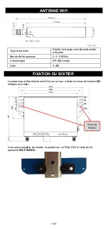
Page 10: ...nde de fréquences 2 4 5 8GHz Connectique RP SMA male Gain 3 dBi FIXATION DU BOITIER Le produit peut être directement fixé sur un mur à l aide de trous de fixation Ø4 intégrés au boitier Il est aussi possible de monter le produit sur un RAIL DIN à l aide du kit optionnel WL FIX RD2 ...

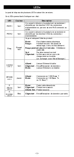
Page 11: ... alimentation électrique Rouge Pendant environ 40s durant le démarrage Vert une fois démarré Rouge pendant plus de 2 minutes Défaillance matérielle Vert Fonctionnement normal Clignotant Le firmware est en cours de chargement ou invalide Le recharger avec WaveManager Link Act LAN 1 2 Vert Allumé Liaison Ethernet établie Clignotant Envoi Réception de données Éteint Liaison Ethernet non établie SPEED...

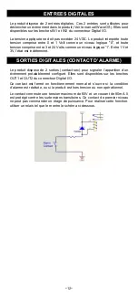
Page 12: ... est indéterminé SORTIES DIGITALES CONTACT D ALARME Le produit dispose de 2 sorties contact sec pour signaler l apparition d un événement préalablement configuré Elles sont disponibles sur les broches OUT1 et OUT2 du connecteur Digital I O Ce contact est fermé en fonctionnement normal et s ouvre si la condition d alarme est réalisée ou si le produit est hors tension ou non opérationnel Le contact ...

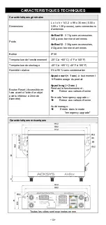
Page 13: ...60 C 4 F à 140 F Température de stockage 40 C à 85 C 40 F à 185 F Humidité relative 5 à 95 sans condensation Bouton Reset Accessible en face avant à l aide d un objet pointu inférieur à 2mm de diamètre Appui court 1 sec à tout moment Redémarrage du produit Appui long 2 sec Pendant le fonctionnement Retour aux valeurs d usine En mode emergency upgrade Retour aux valeurs d usine Au démarrage Entrée ...

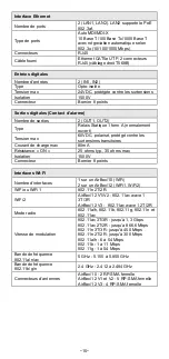
Page 14: ...u mode ad hoc Sécurité WEP WPA WPA2 WPA3 PSK et 802 1x Chiffrement AES TKIP WEP Pour le mode Mesh uniquement supporté avec l interface Wi Fi 4 Topologie réseau 802 11s Sécurité SAE AMPE Alimentation Nombre de sources d alimentation 3 PWR1 PWR2 et PoE Sources PWR1 PWR2 Alimentation redondante DC large plage 9 à 48 VDC protégée contre inversions de polarité Sur connecteur bornier 5 points Source PoE...

Page 15: ...transitoires Courant de charge max 80mA Résistance ON 25 ohms typ 35 ohms max Isolation 1500V Connecteur Bornier 8 points Interfaces Wi Fi Nombre d interfaces 1 sur un AirBox 10 WiFi 2 sur un AirBox 12 WiFi1 WiFi2 WiFi ou WiFi 1 802 11n 2T 2R WiFi 2 AirBox 12 V1 V2 802 11ac wave 1 3T 3R AirBox 12 V3 802 11ac wave 1 2T 2R Mode radio 802 11a h 802 11b 802 11g 802 11n et 802 11ac Vitesse de modulatio...

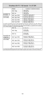
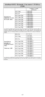
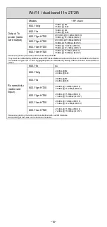
Page 16: ...cause des pertes entre la radio et le connecteur d antenne Ces valeurs sont les puissances sur chaque chaîne d émission Les puissances dites agrégées sur 2 chaînes d émission se calculent en ajoutant 3dB Sensibilité de réception à l entrée de la carte radio 802 11b Non disponible 802 11b g 94 dBm 6M 80 dBm 54M 802 11a 96 dBm 6M 84 dBm 54M 802 11gn HT20 92 dBm 7 2Mbps MCS 0 76 dBm 72 2 Mbps MCS 7 8...

Page 17: ... radio et le connecteur d antenne Ces valeurs sont les puissances pour 1 chaine d émission Les puissances dites agrégées sur 2 ou 3 chaînes d émission se calculent en ajoutant 3dB pour 2 chaînes et 4 8 dB pour 3 chaînes Sensibilité de réception à l entrée de la carte radio Tolérance 2dB 802 11b Non disponible 802 11b g 94 dBm 6M 80 dBm 54M 802 11a 96 dBm 6M 84 dBm 54M 802 11gn HT20 94 dBm MCS 0 77...

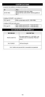
Page 18: ...est conforme à FCC part 15 FCC modular approval ID Z9W RMB L interface WiFi2 est conforme à FCC part 15 FCC modular approval ID TK4WLE900VX FCC modular approval ID TK4WLE600VX ACCESSOIRES OPTIONNELS REFERENCE DESCRIPTION PWS12 UNI PH3 Bloc alimentation AC 110V 220V vers 12 VDC avec un connecteur Phoenix 3 points WL FIX RD2 DIN rail fixing kit Ces 2 références peuvent être commandées séparément ...

Page 19: ...al inputs 2 insulated programmable digital outputs Before starting please check the product kit part listing below Contact immediately your dealer if any item is missing or damaged One AirBox device 1 standard cat 5e straight Ethernet cable 2 WiFi omni directional dual band 2 4 5 GHz antennas for AirBox 10 5 4 WiFi omni directional dual band 2 4 5 GHz antennas for AirBox 12 V2 V3 This quick instal...

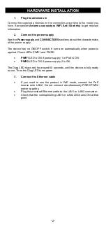
Page 20: ...urns on automatically when power is applied Check LEDs PWR1 and PWR2 PWR1 LED is ON if power supply 1 or PoE is ON PWR2 LED is ON if power supply 2 is ON The Diag LED stays red for around 60 seconds until the device is fully ready to use Then the Diag LED turns green 3 Connect the Ethernet cable If you want to use the product in PoE mode connect the PoE source onto LAN2 Do not connect simultaneous...

Page 21: ... think about changing the IP address of the network interface of the connected PC 5 Configure the product Run the WEB Interface of the product from WaveManager via WEB server button The default page STATUS tab displays the device status Now select the SETUP tab You will be asked for a username and password You must choose the root user No password is required by default You get now access to the s...

Page 22: ...omize your Wireless interface according to The operating mode Access point client bridge Wi Fi parameters 802 11 mode radio channel SSID Wi Fi security parameters WEP WPA WPA PSK WPA2 WPA2 PSK SSID broadcast or not You will find a complete description of all modes in the WaveOS user guide Warning Save your settings by clicking Save Apply Otherwise your settings will be lost if the product has to r...

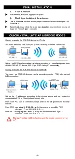
Page 23: ...rk interface according to the default parameters of the ACKSYS AP device 802 11gn SSID acksys no security Quickly evaluate the ACKSYS device in client role You need two ACKSYS devices and a second computer PC2 with a wired LAN connection Set up the IP addresses according to the picture above and set the device connected to PC2 to Client infrastructure role From each PC start a command prompt and r...

Page 24: ...urity match those of the AP Check the radio conditions distance between devices placement of antennas interferences and obstacles to radio waves propagation Try with all securities and encryption settings temporarily disabled Try using the product with factory settings as shown in the Quickly evaluate section Try another radio channel WaveManager doesn t find your device WaveManager only scans the...

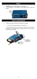
Page 25: ...c object to press the button EARTH GROUNDING There are 2 ways to connect the product to the ground Use the power terminal block on the front panel Use the grounding lug 0 81x6 35 mm on the right side For efficient grounding we recommend using a braided metal wire connected to a female lug not supplied ...

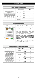
Page 26: ...hey can automatically select the transmission speed 10 Base T 100 Base Tx or 1000 Base T Half Full Duplex It enables to the device to coexist in the network by mitigating the risks of network disruption arising from incompatible technologies LAN2 has a PoE Powered Device built in interface 802 3 af compliant Digital I O connector Digital inputs outputs 8 way terminal block connector Signal name Pi...

Page 27: ... antenna AirBox 12 V3 Interface WiFi2 2T 2R WiFi2 Ant1 RF connector for the 1st antenna WiFi2 Ant 2 RF connector for the 2nd antenna To get the highest benefit of the MIMO technology and its high radio bit rate you must connect all antennas 2 in WiFi1 and 2 3 in WiFi2 Nevertheless in degraded mode it is possible to connect a single antenna for a 2T 2R interface use exclusively Ant1 connector WiFi1...

Page 28: ...mnidirectional swivel Dual band 2 4 5 8GHz Connector RP SMA male Gain 3 dBi PANEL MOUNTING OF THE DEVICE For fixing use the 2 opposites holes of Ø8 present on the case Moreover it is possible to mount the product on a DIN RAIL by using the WL FIX RD2 kit ...

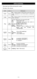
Page 29: ... is off Red Initialization during 40s after power is applied then goes Green Red for more 120s hardware failure Green Ready to use Blinking Firmware in flash is loading or not valid please load new firmware with WaveManager Link Act LAN 1 2 Green On Link on LAN established Flashing Tx Rx activity Off Link on LAN broken SPEED LAN1 2 Yellow On connected in 1000 BASE T Off connected in 100 BASE Tx or...

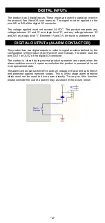
Page 30: ...oduct has two digital outputs in order to signal an alarm defined by the configuration of the product See WaveOS user manual The alarm uses the pins OUT1 or OUT2 of the digital I O connector The contact is closed during normal product operation and opens when the alarm condition occurs It opens as well when the product is powered off or not in an operational state The alarm contact can switch 60V ...

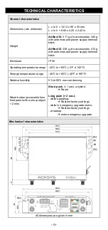
Page 31: ... IP 30 Operating temperatures range 20 C to 60 C 4 F à 140 F Storage temperatures range 40 C to 85 C 40 F à 185 F Relative humidity 5 to 95 non condensing Reset button accessible from front panel with a sharp object 2 mm Short push 1 sec anytime Reset Long push 2 sec while operating Restore factory settings while in emergency upgrade mode Restore factory settings at startup enter emergency upgrade...

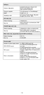
Page 32: ...ure ad hoc or mesh mode Security WEP WPA2 802 1x supplicant AES TKIP WEP by hardware encryption Mesh mode only supported only with WiFi 4 interface Network topology 802 11s Security SAE AMPE Power supply Number of power supply inputs 3 PWR1 PWR2 and PoE PWR1 PWR2 source 9 to 48VDC protected against wire inversion 5 ways terminal block connector PoE source 802 3af 802 3at type 1 class 3 on LAN2 Fea...

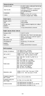
Page 33: ... ohms typ 35 ohms max Isolation 1500V Connector 8 ways terminal block Connector Wi Fi interfaces Number of interfaces 1 for AirBox 10 ou 14 WiFi 2 for AirBox 12 WiFi1 WiFi2 WiFi or WiFi1 AirBox 12 V1 V2 802 11ac wave 1 3T 3R AirBox 12 V3 802 11ac wave 1 2T 2R WiFi2 802 11a h 802 11b 802 11g 802 11n et 802 11ac Radio mode 802 11ac 3T 3R up to 1 3 Gbps 802 11ac 2T 2R up to 866 6 Mbps 802 11n 3T 3R u...

Page 34: ...acted by 2dB because of RF losses between radio card connector and antenna connector The values are given for 1 chain Aggregate power is calculated by adding 3 dB for 2 chains and 4 8 dB for 3 chains Rx sensitivity radio card input 802 11b NA 802 11b g 94 dBm 6M 80 dBm 54M 802 11a 96 dBm 6M 84 dBm 54M 802 11gn HT20 92 dBm 7 2Mbps MCS 0 76 dBm 72 2 Mbps MCS 7 802 11gn HT40 90 dBm 15 Mbps MCS 0 73 d...

Page 35: ...d by 2dB because of RF losses between radio card connector and antenna connector The values are given for 1 chain Aggregate power is calculated by adding 3 dB for 2 chains and 4 8 dB for 3 chains Rx sensitivity radio card input 802 11b Non disponible 802 11b g 94 dBm 6M 80 dBm 54M 802 11a 96 dBm 6M 84 dBm 54M 802 11gn HT20 94 dBm MCS 0 77 dBm MCS 7 802 11gn HT40 93 dBm MCS 0 75 dBm MCS 7 802 11an ...

Page 36: ...our website WiFi WiFi1 interface conforms to FCC part 15 FCC modular approval ID Z9W RMB WiFi2 interface conforms to FCC part 15 FCC modular approval ID TK4WLE900VX FCC modular approval ID TK4WLE600VX OPTIONAL ACCESSORIES REFERENCE CONTENT PWS12 UNI PH3 AC 110V 220V to 12 VDC power adapter with cable terminated by 3 pin terminal block WL FIX RD2 DIN rail fixing kit All items can be ordered separat...

Reviews: