8
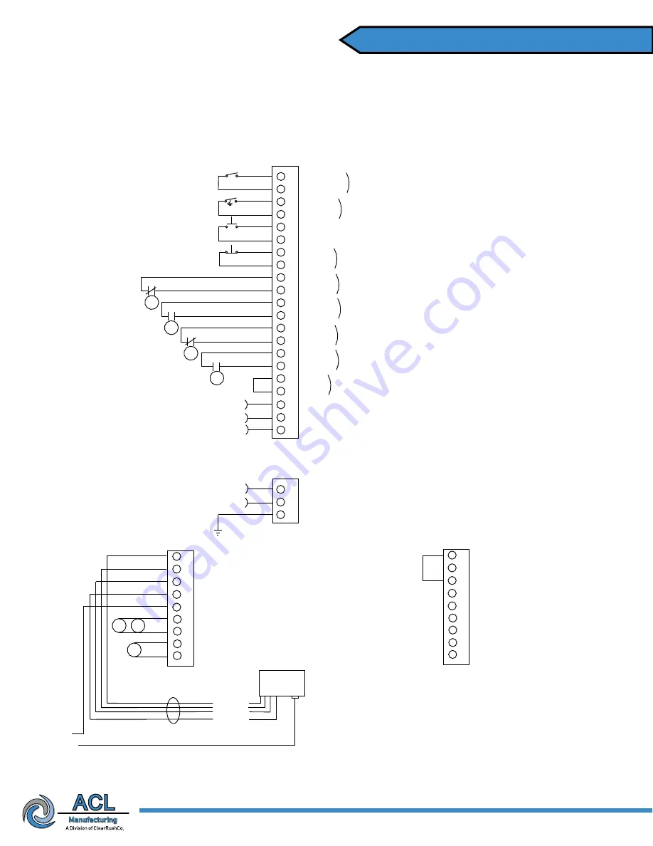
ACL 5500
120/240 VAC
1 Burner System
1
2
3
4
6
7
8
9
10
5
11
12
13
14
15
16
17
18
19
20
21
Proof of Closure
Proof of Closure
Jumper when not in use
Temp Control
Temp Control
Jumper when not in use
Remote Start
Remote Start
Jumper when not in use
Remote S/D
Remote S/D
Hi Press S/D
Hi Press S/D
Jumper when not in use
Lo Press S/D
Lo Press S/D
Jumper when not in use
Hi Temp S/D
Hi Temp S/D
Jumper when not in use
Lo Level S/D
Lo Level S/D
Jumper when not in use
Aux 1 S/D
Aux 1 S/D
Jumper when not in use
Alarm Status NO
Alarm Status COM
Solenoid #2 HOT
Solenoid #2 NEU
Solenoid #1 HOT
Solenoid #1 NEU
(Main)
(Pilot)
Note:
Solenoid O/P Voltage
Equal to Supply Voltage
Aux. S/D
#1
LL
SD
HT
SD
LP
SD
HP
SD
Remote Stop Button
Remote Start Button
Temp Switch
Burner #1
S/D Valve P.O.C.
MUST BE DRY CONTACTS.
MUST BE IN CLOSED POSITION
INITIALLY FOR BURNER TO START
To PLC or RTU
for Remote Status
Ignition
Module
To Ignitor/Flame Rod
25
26
27
28
29
Power
Alarm
Valve
Ground
Bonding Ground
22
23
24
120/240 HOT
120/240 NEU
System Ground
(Power Supply)
Power Supply
120/240 VAC
30
31
32
33
SV
SV
SV
Burner #1 Pilot
1 or 2 Valve System
Alarm Status NC
Solenoid #2 HOT
Solenoid #2 NEU
Solenoid #1 HOT
Solenoid #1 NEU
(Main)
(Pilot)
34
35
36
37
38
Power
Alarm
Valve
Ground
Bonding Ground
39
40
41
42
Note:
Run #18 AWG
for shutdowns
BURNER #1
BURNER #2 (Optional)
Note:
Jumper between
34 & 36 when not in use
To Ignitor/Flame
Rod Ground
Pneumatic
Control Box
Prewired in Control Box
Red
Blue
Brown
Yellow
Note:
If remote mounting of ignition
module is preferred, the ACL 5000R remote
mount kit is available upon request
ACL 5500 Combustion Safety Controller
ACL 5500 Combustion Safety Controller
Yellow
Yellow


