14
INSTALLATION PREPERATION AND OVERVIEW
IF LINE OR PUMP PRESSURE EXCEEDS 70PSI, A PRESSURE REGULATOR WILL BE REQUIRED FOR
THIS SYSTEM
(By-Pass and Pressure Regulator are not supplied)
1.
Pre-measure area required for all components as per sizing.
2.
Shut off main water supply and drain water line.
3.
Cut water line after water meter or pressure tank.
4.
Place Aclarus system in pre-determined area.
5.
Place filter(s) in pre-determined area. (Usually beside Aclarus system)
6.
Install by-pass valves for future use or service.
7.
If required install pressure regulator (not supplied).
8.
Assemble system as required using unions and equipment supplied – NOTE
System is only built to connect components solely at specific locations
9.
Plumb Aclarus system and other components into water supply.
(These components may vary depending on your application)
10.
Install Gas-off chamber as per Drawing #3. (Be sure to apply Teflon to
threads if not already applied)
11.
Using ¼” PVC braided hose, vent gas-off chamber to exterior of dwelling OR
down a drain – if putting to the outside air be sure to not allow it to freeze.
12.
Connect air dryer braided hose with silica gel (provided).
IMPORTANT:
Make sure to connect the top (cap) end of the air dryer to the braided
hose and leave the bottom fitting open to the air.
13.
Ensure the power switch on front of Aclarus head is in the OFF position.
Check Serial Number plate for unit voltage and connect to appropriate
power source.
Summary of Contents for AOWT-7
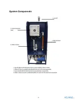
Page 9: ...9 System Components...
Page 10: ...10 NOTE System components and tank may not be exactly as shown...
Page 47: ...47 Appendix Component Specification Sheets Pumps Specifications...
Page 48: ...48...
Page 49: ...49...
Page 50: ...50 Flow Switch Specifications...
Page 51: ...51...
Page 52: ...52 Mazzei Specifications...
Page 53: ...53 Gas Off 1 Specifications...


