English –
2
ENEN
PRODUCT INSTALLATION
3
3.1 • Preliminary checks –
Application limits
Caution! – Before proceeding with installation,
verify the following.
- There are various versions of this product available, each
designed to manage a specific motor torque. Each is de-
signed to automate shutters / awnings / scre ens with spe-
cific dimensions and weight. Therefore, be fore proceed-
ing with installation, to check that the characteristics of
this motor (motor tor que, rotation speed and operating
time) are suitable for automating your shutter / awning
/ screen.
Caution! - Never install a motor with
a greater motor torque than that required to
move your shutter / awning / screen.
Check the diameter of the winding roller. This must be cho-
sen according to the motor torque, as follows:
- for motors that are size (Ø = 45 mm) and have a torque of
up to 30 Nm (included), the minimum inside diameter of
the winding roller must be 52 mm;
- for motors that are size (Ø = 45 mm) and have a torque of
up to 30 Nm (included), the minimum inside diameter of
the winding roller must be 60 mm.
for motors that are size (Ø = 58 mm), the minimum
inside diameter of the winding roller must be 70 mm.
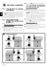
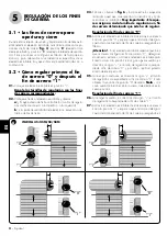
3.2 • Tubular motor installation
To install the product, follow the phases shown in
fig. 5
and
observe the following
warnings
:
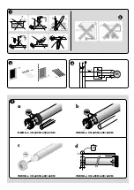
- Incorrect installation can lead to serious injury.
ELECTRICAL CONNECTIONS
4
4.1 • Installing safety devices
in the electrical mains
In compliance with the electric installation rules, in the net-
work that powers the motor, a short circuit protection device
and a disconnection device from the mains electricity must
be envisioned.
Attention! – The disconnection device must al-
low the complete disconnection of the pow-
er supply, in the conditions established by the
over-voltage category III.
The disconnection device must be located in view of the au-
tomation and, if it is not visible, must envision a system that
blocks any accidental or unauthorised re-connection of the
power supply, in order to prevent any danger.
Note – The two devices are not present in the package.
4.2 • Installation of the
pushbutton strip
Recommendations:
• Position the push button control panel in view of the wind-
ing device but away from its moving parts.
• Position the push button control panel on the side of the wind-
ing device, where there is the electric cable coming from the
tubular motor and the mains electricity power supply cable.
• Position the buttons at a height over 1.5 m from the floor.
4.3 • Connecting the motor to a
control pushbutton panel
and the electrical mains
Attention!
• Incorrect connection can cause faults or dangerous situa-
tions, therefore scrupulously respect the instructions given
in this paragraph.
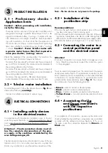
From an electrical perspective, the motor must be perma-
nently powered by means of a permanent connection to the
mains electricity (verify compatibility on the label attached
to the motor). To connect the motor to a push-button control
panel and the mains electricity, refer to
fig. 4
. The connec-
tion cable wires have the following function:
– Brown
= electric ascent or descent phase.
– Black
= electric ascent or descent phase.
– Blue
= Common (normally connected to the Neutral).
– Yellow-Green
= Ground (protective electrical bond-
ing).
4.4 • Associating the Up
and Down movements
with the respective
pushbuttons
On completion of connections, power up the motor and
check whether the Up and Down movements are associated
correctly with the relative control pushbuttons. If this is not
the case, invert the connection between the
Brown
and
Black
wires.


