4A
4. How To Set The Unit
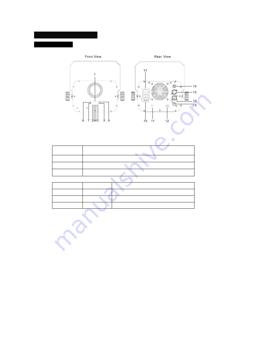
4.1 Control Panel
1. Display
Show the various menus and the selected functions.
Button
2.MENU
To select the programming functions
3.DOWN
To go backward in the selected functions
4.UP
To go forward in the selected functions
5.ENTER
To confirm the selected functions
LED
6.DMX
On
DMX input present
7.MASTER
On
Master Mode
8.SOUND
Flashing
Sound activation
9.SLAVE
On
Slave Mode
10.
Power in
: Power connection to power source.
11.
Safety hook
: Used to connect safety cable to.
12.
Microphone
: Receive music for the sound active.
13.
Only for wireless receiver
: Connect with CA-9 RTX to control the unit for Stand by, Function
and Mode function.
14.
DMX in
: For DMX 512 link, use 3-pin XLR plug cable to input DMX signal.
15.
DMX out
: For DMX 512 link, use 3-pin XLR plug cable to link the next fixture.
16.
Only for remote control:
Connect with CA-8 to control the unit for Stand by, Function and
Mode function.
17.
Power out:
Connect to supply mains power for the next fixture.
Summary of Contents for ColorTec 250 LED-CC60
Page 1: ...User Guide Please read the instruction carefully before using ...
Page 7: ...6A ...
Page 13: ...12A 5 4 DMX 512 Configuration 3 8 Channels Mode ...
Page 17: ......
Page 18: ......


