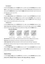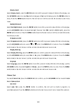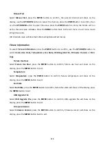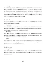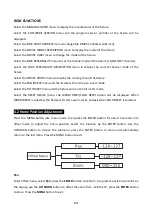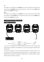
3. The DMX output and input connectors are pass-through to maintain the DMX circuit, when one
of the units’ power is disconnected.
4. Each lighting unit needs to have a DMX address to receive the data by the controller. The address
number is between 1-512.
5. The end of the DMX 512 system should be terminated to reduce signal errors.
6. 3 pin XLR connectors are more popular than 5 pins XLR.
3 pin XLR: Pin 1: GND, Pin 2: Negative signal (-), Pin 3: Positive signal (+)
5 pin XLR: Pin 1: GND, Pin 2: Negative signal (-), Pin 3: Positive signal (+), Pin4, Pin5 not used.
5.2 Address Setting
If you use a universal DMX controller to control the units, you have to set DMX address from 1 to
512 so that the units can receive DMX signal.
Press the MENU button to enter menu mode, select
DMX Settings, press the ENTER button to
confirm, use the UP/DOWN button to select DMX Address, press the ENTER button to confirm, the
present address will blinking the display, use the UP/DOWN button to adjust the address from 001
to 502/499/498/499, press the ENTER button to store. Press the MENU button back to the last menu
or idling let the unit idle one minute to exit menu mode.
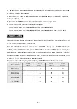
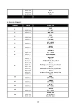
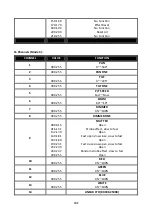
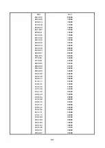
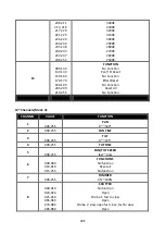
Please refer to the following diagram to address your DMX512 channel for the first 4 units.
Channel mode
Unit 1
Address
Unit 2
Address
Unit 3
Address
Unit 4
Address
11 channels
1
12
23
34
14 channels
1
15
29
43
15 channels
1
16
31
46
14* channels
1
15
29
43
15E
Summary of Contents for Diabolo
Page 1: ......
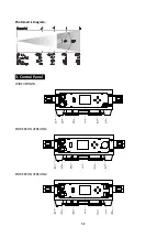
Page 6: ...Photometric Diagram 3 Control Panel WIRE VERSION POWERCON VERSION1 POWERCON VERSION2 5E ...
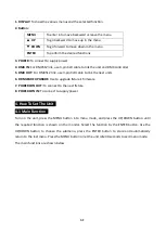
Page 8: ...7E ...
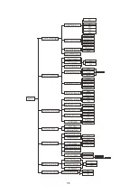
Page 27: ...26E ...

