background image


Page


2.4


EXTERNAL


WIRE


GUIDE


Installation


Manual


|


September


2013


©


Copyright


2013


|


All


Rights


Reserved


Acmeda


(International


Group)


PART


C


WIRE


GUIDE


INSTALLATION


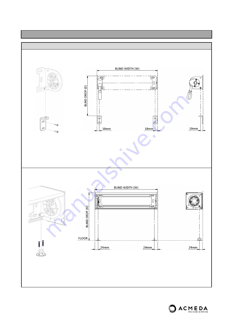
STEP


1


MARK


&


SECURE


BOTTOM


WIRE


GUIDE


FIXING


TO


WALL


OR


FLOOR


OPEN


BLIND


SYSTEM


NOTE:


Dimensions


refer


centre


of


wire


and


apply


to


both


Face


Fixing


and


Floor


Fixing


installations.


BOX


120


SYSTEM


NOTE:


Dimensions


refer


centre


of


wire


and


apply


to


both


Face


Fixing


and


Floor


Fixing


installations.


X


2


Brackets


X


2


Plates


Summary of Contents for BOX 120

Page 1: ...EXTERNAL WIRE GUIDE INSTALLATION MANUAL September 2013...

Page 2: ...sible to ensure that supporting structures are sound and can adequately support the load The Installer is responsible to ensure that the devises used to anchor the product to the supporting structure...

Page 3: ...REQUIRED Saw Saw Drill Screw Driver Philips Head Flat Head Jaw Pliers Allen Key Set Mallet Scissors Punch tool template Measuring Tape Pencil ADDITIONAL ITEMS REQUIRED NOT SUPPLIED To assemble an EXT...

Page 4: ...quare 120 Required Installation Items 3 Complete Blind 4 Wire Guide Components 1 Brackets 2 Box Square 120 Required Installation Items Bracket Spacers x2 Adjustable Stop x2 3 Complete Blind 4 Wire Gui...

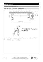
Page 5: ...TRUCTURAL SUPPORT Check the Installation Space and ensure adequate clearance is provided for the system NOTE For Top Fix Installations allow 5mm from the wall to the edge of the bracket to provide cle...

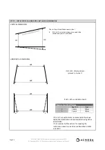
Page 6: ...C If W2 W1 see table for limits Maximum width difference Box 120 Open X 16mm 10mm Y 16mm 10mm If X and Y are within limits as indicated in the above table then installation can be completed using W1 a...

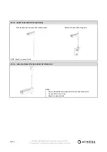
Page 7: ...LL CEILING USING APPROPRIATE FIXINGS TO SUIT APPLICATION OPEN BLIND SYSTEM FACE FIX TOP FIX NOTE Ensure brackets are installed aligned and level Refer to deductions for bracket positioning BOX 120 SYS...

Page 8: ...RE GUIDE INSTALLATION STEP 1 MARK SECURE BOTTOM WIRE GUIDE FIXING TO WALL OR FLOOR OPEN BLIND SYSTEM NOTE Dimensions refer centre of wire and apply to both Face Fixing and Floor Fixing installations B...

Page 9: ...G BRACKET NOTE Ensure both Terminals are attached to brackets FLOOR FIX ROUND EYE PLATE i Remove 1 Nut 2 Washers From Stud Terminal ii Thread Turnbuckle Set onto Terminal iii Remove Pin Clip iv Positi...

Page 10: ...up STEP 3 INSERT WIRE GUIDE FLOAT ONTO WIRE Feed Floating End Cap onto Wire at both ends NOTE Repeat on opposite side Allow End Cap to Slide along wire STEP 4 ADD ADJUSTABLE STOP FOR BOX 120 SYSTEM ON...

Page 11: ...minal Measure cut wire approximately 5 10mm above terminal Tighten grub screw securely to retain wire ensure thread of grub screw does not strip STEP 6 ADJUST SECURE ADJUSTABLE STOP TO WIRE GUIDES FOR...

Page 12: ...RT D BLIND INSTALLATION STEP 1 INSERT CONTROL END FIRST THEN SWING IDLER END INTO ADAPTOR GEAR CONTROL Ensure Idler Pin Locks into Adaptor STAR HEAD MOTOR FOR STAR HEAD MOTOR ONLY Remove retaining scr...

Page 13: ...order to lock the Motor in position STEP 3 INSERT FLOATING END CAPS INTO END CAP HOUSING Before applying tension to wire guides insert end cap float into weight bar end caps If more clearance space is...

Page 14: ...13 All Rights Reserved Acmeda International Group PART E BOX COVER INSTALLATION FOR BOX 120 SYSTEM ONLY STEP 1 SWING BOX COVER INTO PLACE Ensure Cover clips to tab IF the lip of the cover is not locat...

Page 15: ...Page 2 11 EXTERNAL WIRE GUIDE Installation Manual September 2013 Copyright 2013 All Rights Reserved Acmeda International Group STEP 2 FIX COVER WITH SCREW OR RIVET OPTIONAL...

Page 16: ...IX 1 Pull Swage Terminal down to remove slack and hand tighten bottom nut until contact with bracket 2 Apply tension by holding Swage Terminal still and rotating bottom nut as required No Of Rotations...

Page 17: ...led with care 2 Blind does not fully open jams Position of wire guides at base is incorrect Check if wire guide fixing at floor base are positioned in line with the Top Terminal If fixing is too far i...

Reviews: