background image

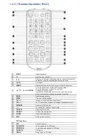
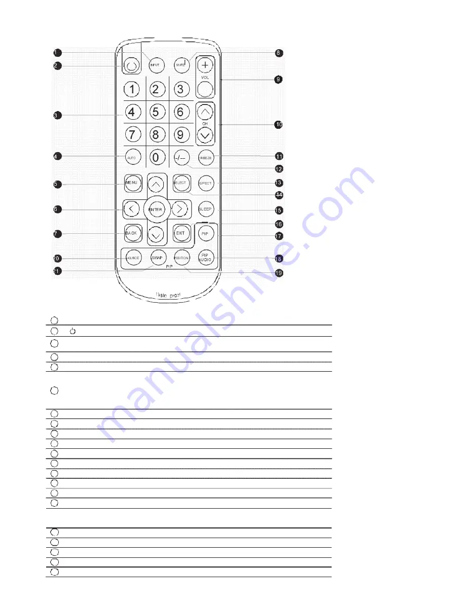
< 2.3 > Remote Controller ( RC-2 )


8


INP UT 

MUTE


VOL


9


3


6


CH


10


9


AUTO 

-/-- 

F REE ZE


11


12


ME NU 

SE LECT 

AS P ECT


13


14


ENTE R 

SLEEP


15


16


BA CK 

EXIT 

PIP


17


PIP


20 

S OURCE 

SWAP 

POS ITION 

AUDIO


18


PIP


21 

19


r


INPUT 

Select the source


Switches on or off the TV


0 - 9 

Only use in TV mode. Select channels. For channel numbers 10 
and above, enter the second digit within two seconds.


AUTO 

Auto  adjust


MENU 

Display the menu on the screen or go to the previous menu 

Go to the upper menu or select the previous value /


Go to the next menu or select the next value /


  / 

  / 

  / 

ENTER 

Decrease the setting value /


Increase the setting value or enter to the select item setting


Enter to the select item settings or excude the setting


BACK 

Back to previous value


MUTE 

Turn on or off the speaker


Vol + I - 

Increase  or  decrease the  speaker volume


10 

CH + I - 

For TV model  only,  increase or  decrease the channel number


11 

FREEZE 

Reserve for OEM model


12 

- I -- 

For  setting input single or  double digits


13 

ASPECT 

Adjust the screen size


14 

SELECT 

To select the existing item


15 

SLEEP 

Select the sleeping time


16 

EXIT 

Exit the menu or cancel


PIP functions


17


PIP


Picture in picture


18


PIP AUDIO


To set the audio of in PIP mode


19


POSITION


To set the screen position in PIP mode


20


SOURCE


PIP Source


21


SWAP


Swap screen in PIP mode


Summary of Contents for APW5170

Page 1: ...trial Monitors User Manual All rights reserved Product description and product specifications are subject to change without notice For lastest product information please visit Acnodes website at www acnodes com 14628 Central Ave Chino CA91710 Tel 909 597 7588 Fax 909 597 1939 Copyright 2015 Acnodes Corp ...

Page 2: ...open the chassis Opening it yourself could damage the equipment and invali date its warranty If any part of the equipment becomes damaged or stops functioning have it checked by qualified service personnel What the warranty does not cover Any product on which the serial number has been defaced modified or removed Damage deterioration or malfunction resulting from Accident misuse neglect fire water...

Page 3: ...ller 2 1 Product Specifications 2 2 On screen Display Operation OSD 2 3 Remote Controller RC 2 P 6 7 P 8 9 P 10 Part 3 Options 3 1 Option Table 3 2 3G HD SD SDI Broadcast grade input 3 3 MCS Multi display control solution 3 4 X17 Touchscreen Resistive Capacitive 3 5 48V 24V or 12VDC power 3 6 MIL type or lockable connector 3 7 TV Analog P 11 P 12 P 13 P 14 P 15 P 16 P 17 ...

Page 4: ...onitors and monitor screens can scratch the LCD display or strip off the finish Do not spray any kind of liquid directly onto the screen or case of your monitor Spraying liquids directly onto the screen or case can cause damage which is not covered under warranty Do not use paper towels or abrasive pads to clean your monitor Using an abrasive pad or any wood based paper product such as paper towel...

Page 5: ...Remote controller X 1 Mounting hardware X 1 pack Mounting bracket x 4 pcs M4 6mm screw x 8 pcs M4 50mm screw x 8 pcs Standard IIO An abundance of input connections that include HDMI DVI D VGA S Video BNC and audio On chip Faroudja DCDi Cinema processing out in in Video PC HDMI VGA DVI D Audio Power BNC S Video ...

Page 6: ...glass 4 6mm aluminum front bazel 5 Audio speaker pair 6 LCD membrane 7 Remote sensor Rear view Model Product Dimension W x D x H Packing Dimension W x D x H Net Weight Gross Weight APW5170 469 x 57 x 331 mm 18 4 x 2 2 x 13 inch 615 x 113 x 523 mm 24 2 x 4 4 x 20 6 inch 5 5 kg 12 1 lbs 8 kg 17 6 lbs ...

Page 7: ... 1 2 Dimension APW 5170 Front View Side View Rear View UNIT mm 1mm 0 03937 inch Bottom View ...

Page 8: ... APW 5170 1 Mounting bracket x 4 pcs 2 M4 6mm screw x 8 pcs 3 M4 50mm screw cs Hardware set part no UV BK 2 Steps Install 4 mounting brackets with 8 x M4 6mm screws Adjust the LCD panel with 8 x M4 50mm screws and fix it on the surface ...

Page 9: ... APW 5170 17 Industrial Panel Mount Widescreen LCD 1 3 VESA mount Installation APW 5170 M4 screw VESAmount 100 100mm Hardware and M4 4 pcs for VESA mount are not provided ...

Page 10: ...coating Surface hardness 3H Backlight Type LED MTBF hrs 20 000 Video Connectivity Digital HDMI HDMI 1 1 CEA 861 D DVI DVI D TMDS single link Analog VGA Analog 0 7Vp p Composite RCA NTSC PAL S Video 4 pin NTSC PAL Plug Play DVI VGA VESA EDID structure 1 3 Synchronization VGA Separate Composite SOG Audio Connectivity Audio Input Connector 3 5mm stereo jack Impedance Power level 30kK 750mV Audio Outp...

Page 11: ...x 4 4 x 20 6 inch Net Weight 5 5 kgs 12 1 lbs Gross Weight 8 kgs 17 6 lbs Applicable Format DVI D VGA Input PC Signal 1920 x 1200 x 60Hz 1920 x 1080 x 60Hz 1280 x 1024 x 60 75Hz 1280 x 960 x 60Hz 1280 x 768 x 60 75Hz 1152 x 864 x 75Hz 1024 x 768 x 60 70 75Hz 848 x 480 x 60Hz 800 x 600 x 60 72 75Hz 720 x 400 x 70Hz 640 x 480 x 60 72 75Hz 640 x 400 x 70Hz 640 x 350 x 70Hz HDMI Input PC Signal Same a...

Page 12: ...el of the screen image Contrast Adjust the difference between the image background black level and the foreground white level Hue Adjust the screen hue value Saturation Adjust the saturation of the image color Picture size Adjust the image size Color temp Standard Cool Warm User to choose Noise reduce Reduce the noise of the image Sharpness Adjust the image from weak to sharp 2 PC Auto adjust Auto...

Page 13: ...g sound 5 MISC Language Select the language in which the OSD menu is displayed English Sleep timer Set the off time PIP mode Adjust picture in picture setting PIP position Enter into PIP position PIP source Enter into the Sub source and sound source System reset Return the adjustment back to factory setting Information Select for Help 4 TV Auto search Automatically search Manual search Search the ...

Page 14: ...or select the next value 6 ENTER Decrease the setting value Increase the settingvalue or enter to the select item setting Enterto the select item settings or excude the setting 7 BACK Backto previousvalue 8 MUTE Turn on or off the speaker 9 Vol I Increase or decrease the speaker volume 10 CH I For TV model only increase or decrease the channel number 11 FREEZE Reserve forOEM model 12 I For setting...

Page 15: ... Part 3 Options 3 1 Option Table Options APW PMW SDI Touchscreen MCS multi display control DC Power MIL type lockable connector TV Analog The user can only select either SDI or MCS inputs ...

Page 16: ...p p 75 ohm 3G SDI OUT BNC x 1 Active through equalized relocked StandardCompliance Video SMPTE 425M 274M 296M 125M ITU R BT 656 Audio SMPTE 299M 272M C Compatible Video Format 3G SDI 1080p 60 50Hz 4 2 2 1080p 30 25 24Hz 4 4 4 1080i 60 50Hz 4 4 4 720p 60 50Hz 4 4 4 HD SDI 1080p 30 25 24Hz 4 2 2 1080i 60 50Hz 4 2 2 720p 60 50Hz 4 2 2 SD SDI 480i 60Hz 4 2 2 ITU R BT 656 576i 50Hz 4 2 2 Compatible Aud...

Page 17: ...eters Designed for use with various LCD displays Acnodes provides a MCS input module without using additional space or power and it comes standard with a 2 year warranty MCS RS 232C Set switch For the 1st and last display push the set switch upward 15 feet serial cable over 15 feet extender required For other daisy chain displays push the set switch downward LINK OUT IN OUT IN OUT IN OUT RJ 45 jac...

Page 18: ...s Response Time 15 ms 20 ms OpticalTransmittance 80 3 92 2 Surface Hardness 3H 9H Haze 8 3 7 Glass 2 2 0 2 mm 2 8 mm 10 Connector USB Type A Compatibility Windows 7 XP Vista Linux USB touchscreen package includes 1 x 6ft USB cable quick reference guideline and CD disc For detailed information please refer to the attached CD disc As the touchscreen unit is not made of toughened glass please handle ...

Page 19: ...Step 1 Run the bundled CD disc Step 2 Double click the Setup exe Step 3 Follow the installation instruction to finish the setup Step 4 After installation run the TouchKit program the 4 point calibration Please do the initial calibration after the first setup ...

Page 20: ...ng Input voltage 12 Volt 24 Volt 48 Volt Input range 9 18V 18 36V 36 75V Input current No load 50 mA 50 mA 50 mA Full load 4950 mA 2450 mA 1220 mA Output rating Output voltage 12 Volt 12 Volt 12 Volt Output current 4 16A 4 16A 4 16A Efficiency 84 85 85 ...

Page 21: ...VGA connector types with varying design characteristics to meet cost considerations and to provide users with the most design flexibility possible For more information please contact us Input Part no Standard Lockable Connector DC Power Male YM Ext 461CP001 D type 3W3 USB LUSB A111 00 MIL type or Lockable connectors above can be integrated with our LCD displays Sale service just for connectors not...

Page 22: ...ns TV Analog Power BNC S Video Audio HDMI TV DVI D VGA out in in Video PC 1 For TV option casing dimensions will be changed 2 For RC 2 remote controller specifications please refer to P 14 out in Video in PC HDMI ...

Reviews: