PC 6150/FPC6150 User’s
10
Hardware Installation
Manual
C h a p t e r 2
Hardware Installation
The PC6150 / FPC6150 provides lots of flexible ways for you to
select different configuration such as CPU, CD-ROM and more. The
chapter will show you how to install the hardware. It includes:
f
CPU
f
CD-ROM
f
VGA
f
DRAM
f
Add-on Card
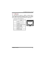
Ethernet
f
f
f
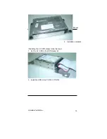
Hard Disk
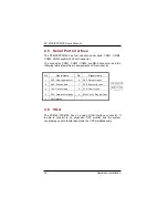
Serial Port
f
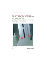
Mountings
2.1 CPU and DRAM Installation
The standard PC6150 / FPC6150 system was designed Pentium M
level CPUs. The build-in CPU board provides one 184-pin DDR
DIMM socket that supports system memory up to 1GB. And, there
is one mini-PCI type-III Socket.
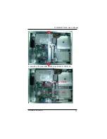
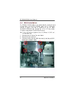
When upgrading the CPU, DRAM, or PCI, refer to the following
instructions and illustration:
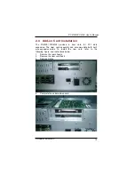
1.
Unscrew screws to remove the rear chassis.
2.
Remove the riser card fix kit.
Summary of Contents for FPC 6150
Page 1: ...PC6150 FPC6150 15 TFT Touch Panel Computer User s Manual...
Page 2: ......
Page 7: ...3 This page does not contain any information...
Page 11: ......
Page 12: ......
Page 18: ...6 Introduction PC 6150 FPC 6150 User s Manual...
Page 21: ......
Page 23: ......
Page 35: ...Hardware Installation 21 PC6150 FPC6150 User s Manual...
Page 39: ...PC6150 FPC6150 User s Manual Driver Installation 25 4 Select the Standard Calibrate tab...
Page 43: ...PC6150 FPC6150 User s Manual Driver Installation 29 This page does not contain any information...


