background image

FPC 8059 User’s Manual


Hardware Installation 

11 


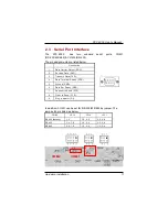
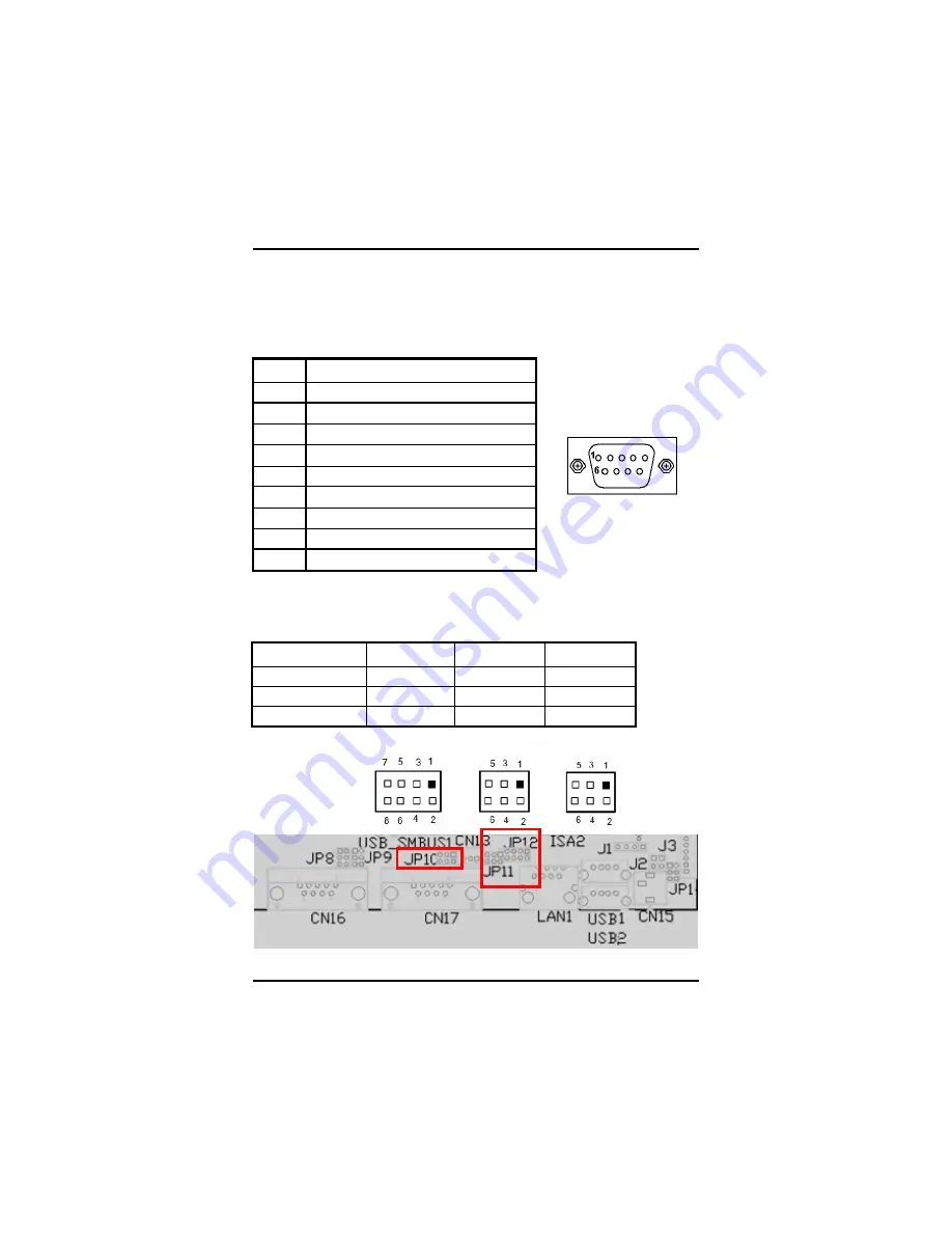
2.3  Serial Port Interface


The 

FPC 8059 

has 

two 

onboard 

serial 

ports, 

COM1 

(RS-232/422/485) & COM2 (RS-232). 


The pin assignments are listed below: 


Desc rip tion


1


Data  Ca rrier  Detect  (DCD)


2


Rec eive  Da ta  (RXD)


3


Tr ans mit  Data  (TXD)


4


Data  Terminal  Re ad y  (DTR)


5


Ground  (GND) 


6


Data  Set  Ready  (DSR)


7


Re ques t  to  Se nd  (R TS)


8


Clear  to  Send  ( CTS )


9


Ring  I ndic ato r  (R I)


In addition, COM1 can be set for RS-232/422/485 by jumper. The 
jump setting is listed as below: 

COM1


JP12


JP10


JP11


RS-232 (default)


1- 2


3-5,  4-6


3-5,  4 -6


RS-422


3- 4,  7 -8


1-3,  2-4


1-3,  2 -4


RS-485


5- 6,  7 -8


1-3,  2-4


1-3,  2 -4


COM2 

COM1


Summary of Contents for FPC 8059

Page 1: ...FPC 8059 5 7 VGA TFT Fan less Touch Panel PC User s Manual ...

Page 2: ......

Page 3: ...document Acnodes Corp makes no commitment to update or to keep current the information contained in this manual Acnodes Corp reserves the right to make improvements to this document and or product at any time and without notice No part of this document may be reproduced stored in a retrieval system or transmitted in any form or by any means electronic mechanical photocopying recording or otherwise...

Page 4: ...ever there is no guarantee that interference will not occur in a particular installation If this equipment does cause harmful interference to radio or television reception which can be determined by turning the equipment off and on the user is encouraged to try to correct the interference by one or more of the following measurers 1 Reorient or relocate the receiving antenna 2 Increase the separati...

Page 5: ...the FPC 8059 is properly grounded 4 The brightness of the flat panel display decreases with usage However hours of use vary depending on the application environment 5 Turn OFF the system power before cleaning Clean the system using a cloth only Do not spray any liquid cleaner directly onto the screen The FPC 8059 comes with a touch screen Although the touch screen is chemical resistant it is recom...

Page 6: ...ge any static electricity on your body When handling boards and components wear a wrist grounding strap available from most electronic component stores Trademarks Acknowledgments Acnodes Corp is a trademark of Acnodes Corp IBM PC AT PS 2 VGA are trademarks of International Business Machines Corp Intel and Pentium are trademarks of Intel Corp MS DOS Microsoft C and Quick BASIC are trademarks of Mic...

Page 7: ...3 This page does not contain any information ...

Page 8: ...d 2 1 2 2 I O System 2 1 2 3 System Specification 3 1 3 Dimensions 3 1 4 I O Outlets 5 1 5 Package list 6 C h a p t e r 2 7 Hardware Installation 7 2 1 CompactFlash Card Installation 8 2 2 PC 104 Installation 9 2 3 Serial Port Interface 10 2 4 Ethernet 11 2 5 Mounting Way Panel mount 11 C h a p t e r 3 12 Windows CE Net 12 3 1 Survey Form 12 3 2 Calibrate Touch Screen 12 Table of Contents vii ...

Page 9: ......

Page 10: ......

Page 11: ...ption The FPC 8059 is a 5 7 fan less TFT VGA touch panel computer It is equipped with CISI based low power consumption processor AMD LX800 By supporting the option of external battery set the FPC 8059 can continue system operation if a main power shortage ever happens In addition the PC 104 and Mini PCI slots are reserved for expansion availability The FPC 8059 supports Compact Flash card and is t...

Page 12: ...artview and customer CMOS backup f System Memory One 184 pin DDR DIMM Maximum up to 1GB 1 2 2 I O System f Standard I O 2 x serial ports 1 x RS 232 1 x RS 232 422 485 2 x USB Ports 2 0 compliant f Ethernet Equipped with 1 x RJ 45 for 10 100 base T f Audio Realtek AC 97 codec audio Line out f Expansion Equipped with 1 x Mini PCI 1 x PC 104 f Compact Flash Socket One Compact Flash Type II Socket ...

Page 13: ...t weight 2 0 Kgs f Dimension main body size 208 5 x 167 3 x 66 5 mm f Operating temperature O to 45 C Relative umidity 50 f Relative humidity 10 to 85 40 C non condensing f Altitude 10 000 ft 3 000 meters f Vibration operating 5 to 500 Hz 1 G random f Shock operating 10 G peak acceleration 11 msec duration 1 3 Dimensions The following diagrams show the dimensions and outlines of FPC 8059 ...

Page 14: ...4 Introduction FPC 8059 User s Manual ...

Page 15: ...er s Manual 1 4 I O Outlets The following figure shows the I O locations of the FPC 8059 1 Power Switch 6 LAN 2 DC power connector 7 USB 2 0 x 2 3 COM 2 RS 232 8 Line out 4 COM 1 RS 232 422 485 9 CompactFlash card 5 PC 104 slot ...

Page 16: ...059 User s Manual 1 5 Package list When you receive the FPC 8059 there are following items in the package If you can not find it please contact Acnodes Corp distributors 1 FPC 8059 x 1 2 Panel mount kit x 6 3 Driver CD x1 ...

Page 17: ......

Page 18: ...tallation The FPC 8059 provides rich I O ports and flexible expansions for you to meet different demand such as PCMCIA WLAN module and so on The chapter will show you how to install the hardware It includes f Compact Flash Card f PC 104 f Serial Port f Ethernet f Mounting Way ...

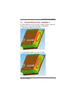
Page 19: ... 2 1 CompactFlash Card Installation FPC 8059 offers one CF slot for users to install Compact Flash card Please refer to the following instructions and illustration 1 Remove the rubber cover at left side 2 Install Compact Flash card in the FPC 8059 ...

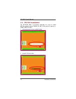
Page 20: ...allation 2 2 PC 104 Installation The FPC 8059 offers a convenient expansion for users to install PC 104 module such as PCMCIA WLAN COM port card and so on Please follow the steps 1 Unscrew screws to remove the bracket 2 Install PC 104 module ...

Page 21: ...ta Carrier Detect DCD 2 Receive Data RXD 3 Transmit Data TXD 4 Data Terminal Ready DTR 5 Ground GND 6 Data Set Ready DSR 7 Request to Send RTS 8 Clear to Send CTS 9 Ring Indicator RI In addition COM1 can be set for RS 232 422 485 by jumper The jump setting is listed as below COM1 JP12 JP10 JP11 RS 232 default 1 2 3 5 4 6 3 5 4 6 RS 422 3 4 7 8 1 3 2 4 1 3 2 4 RS 485 5 6 7 8 1 3 2 4 1 3 2 4 COM2 CO...

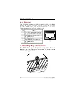
Page 22: ...in assignment of the RJ 45 is listed below Pin Signal TX Data transmission positive 1 TX Data transmission negative 2 1 2 3 4 5 6 7 8 Rx Data reception positive 3 RJ45 termination 4 RJ45 termination 5 Rx Data reception negative 6 RJ45 termination 7 RJ 45 RJ45 termination 8 2 5 Mounting Way Panel mount The FPC 8059 is designed for panel mount application To mount the FPC 8059 the standard set of mo...

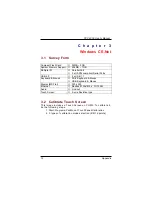
Page 23: ...x USB 1 1 Keyboard Mouse e PS 2 Keyboard Mouse e USB Keyboard Mouse Display MS Flat e 320 x 240 Ethernet e Realtek 8139x 810x 10 100M Audio e Line out Touch Screen e 5 wire Resistive type 3 2 Calibrate Touch Screen This image includes a Touch Screen on COM3 To calibrate it do the following steps 1 Start Programs PenMount TouchPanel Calibration 2 3 types of calibration mode selection 4 9 16 points ...

Reviews: