Chapter 2 Hardware Configuration
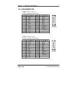
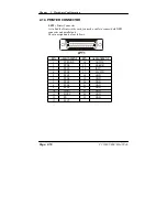
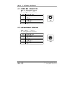
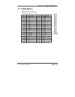
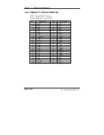
2-14. PRINTER CONNECTOR
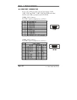
LPT1 :
Printer Connector
As to link the Printer to the card, you need a cable to connect both DB25
connector and parallel port.
The pin assignments are as follows :
LPT1
PIN ASSIGNMENT
PIN
ASSIGNMENT
1 STROBE
14
AUTOF-
2 PPD0
15
ERROR
3 PPD1
16
INIT-
4 PPD2
17
SLCTIN
5 PPD3
18
GND
6 PPD4
19
GND
7 PPD5
20
GND
8 PPD6
21
GND
9 PPD7
22
GND
10 ACK-
23
GND
11 BUSY
24
GND
12 PE
25
GND
13 SLCT
Page: 2-18
PC 1060 USER
’
S MANUAL
Summary of Contents for PC 1060
Page 1: ...USER MANUAL PC 1060 VIA Eden Low Power 10 4 PanelPC System...
Page 9: ...Chapter 1 Introduction 1 2 CASE ILLUSTRATION PC 1060 USER S MANUAL Page 1 3...
Page 10: ...Chapter 1 Introduction Page 1 4 PC 1060 USER S MANUAL...
Page 90: ...Appendix A System Assembly EXPLODED DIAGRAM FOR WHOLE SYTEM UNIT Page A 2 PC 1060 USER MANUAL...
Page 94: ...Appendix A System Assembly EXPLODED DIAGRAM FOR FRONT PANEL Page A 6 PC 1060 USER MANUAL...
Page 96: ...Appendix B Technical Summary BLOCK DIAGRAM Page B 2 PC 1060 USER MANUAL...

