Chapter 2 Hardware Configuration
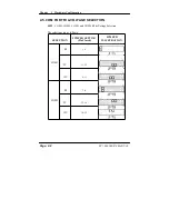
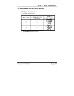
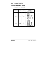
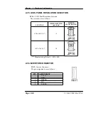
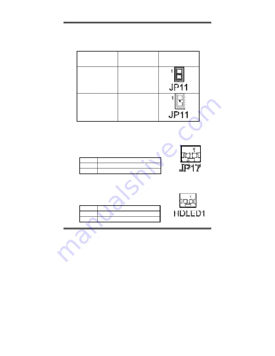
2-20. ONBOARD AUDIO SELECTION
JP11
: Onboard Audio Selection
The selections are as follows:
FUNCTION
JUMPER SETTING
(pin closed)
JUMPER
ILLUSTRATION
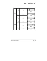
On 1-2
Off open
*** Manufacturing Default – On.
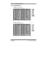
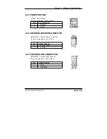
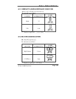
2-21. RESET CONNECTOR
JP17 :
Reset Connector.
The pin assignment is as follows :
PIN ASSIGNMENT
1 GND
2 RSTSW
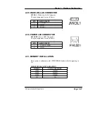
2-22. HDD LED CONNECTOR
HDLED1 :
HDD LED Connector
The pin assignment is as follows :
PIN ASSIGNMENT
1 HD_LED_PWR
2 HD_LED
Page: 2-22
PC 1060 USER
’
S MANUAL
Summary of Contents for PC 1060
Page 1: ...USER MANUAL PC 1060 VIA Eden Low Power 10 4 PanelPC System...
Page 9: ...Chapter 1 Introduction 1 2 CASE ILLUSTRATION PC 1060 USER S MANUAL Page 1 3...
Page 10: ...Chapter 1 Introduction Page 1 4 PC 1060 USER S MANUAL...
Page 90: ...Appendix A System Assembly EXPLODED DIAGRAM FOR WHOLE SYTEM UNIT Page A 2 PC 1060 USER MANUAL...
Page 94: ...Appendix A System Assembly EXPLODED DIAGRAM FOR FRONT PANEL Page A 6 PC 1060 USER MANUAL...
Page 96: ...Appendix B Technical Summary BLOCK DIAGRAM Page B 2 PC 1060 USER MANUAL...

