Chapter 2 Hardware Configuration
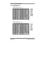
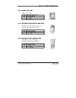
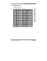
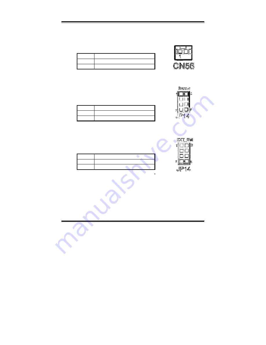
2-23. POWER BUTTON
CN56
: Power Button
The pin assignments are as follows:
PIN ASSIGNMENT
1 PW BN
2 GND
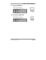
2-24. EXTERNAL BUZZER CONNECTOR
JP14 (1-2) :
External Buzzer Connector.
The pin assignments are as follows :
PIN ASSIGNMENT
1 E_BUZ_PWR
2 E_BUZ
2-25. EXTERNAL SMI CONNECTOR
JP14 (7-8) :
External SMI Connector.
The pin assignments are as follows :
PIN ASSIGNMENT
7 GND
8 EXTSMIJ
PC 1060 USER
’
S MANUAL
Page: 2-23
Summary of Contents for PC 1060
Page 1: ...USER MANUAL PC 1060 VIA Eden Low Power 10 4 PanelPC System...
Page 9: ...Chapter 1 Introduction 1 2 CASE ILLUSTRATION PC 1060 USER S MANUAL Page 1 3...
Page 10: ...Chapter 1 Introduction Page 1 4 PC 1060 USER S MANUAL...
Page 90: ...Appendix A System Assembly EXPLODED DIAGRAM FOR WHOLE SYTEM UNIT Page A 2 PC 1060 USER MANUAL...
Page 94: ...Appendix A System Assembly EXPLODED DIAGRAM FOR FRONT PANEL Page A 6 PC 1060 USER MANUAL...
Page 96: ...Appendix B Technical Summary BLOCK DIAGRAM Page B 2 PC 1060 USER MANUAL...

