Chapter 2 Hardware Configuration
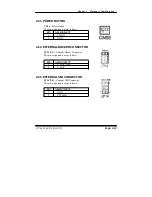
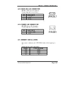
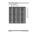
2-29. WAKE-ON-LAN CONNECTOR
JWOL1 :
Wake-On-LAN Connector
The pin assignments are as follows :
PIN ASSIGNMENT
1 +5VSB
2 GND
3 WOL1
2-30. POWER LED CONNECTOR
PWLED1:
Power LED Connector.
The pin assignments are as follows :
PIN ASSIGNMENT
1 PWLED_PWR
2 GND
2-31. MEMORY INSTALLATION
This system is enhanced with 1 DDR DRAM banks, which support up to
1G.
DRAM BANK CONFIGURATION
DIMM 1
TOTAL MEMORY
128M 128MB
256M 256MB
512M 512MB
1G 1G
PC 1060 USER
’
S MANUAL
Page: 2-27
Summary of Contents for PC 1060
Page 1: ...USER MANUAL PC 1060 VIA Eden Low Power 10 4 PanelPC System...
Page 9: ...Chapter 1 Introduction 1 2 CASE ILLUSTRATION PC 1060 USER S MANUAL Page 1 3...
Page 10: ...Chapter 1 Introduction Page 1 4 PC 1060 USER S MANUAL...
Page 90: ...Appendix A System Assembly EXPLODED DIAGRAM FOR WHOLE SYTEM UNIT Page A 2 PC 1060 USER MANUAL...
Page 94: ...Appendix A System Assembly EXPLODED DIAGRAM FOR FRONT PANEL Page A 6 PC 1060 USER MANUAL...
Page 96: ...Appendix B Technical Summary BLOCK DIAGRAM Page B 2 PC 1060 USER MANUAL...

