Chapter 4 Award BIOS Setup
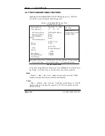
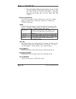
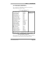
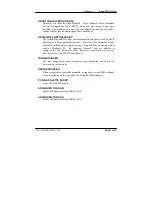
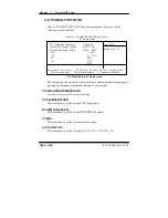
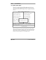
ONCHIP IDE CHANNEL 0 / 1 :
The chipset contains a PCI IDE interface with support for two IDE
channels. Select Enabled to activate the secondary IDE interface. Select
Disabled to deactivate this interface.
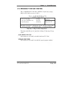
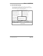
IDE PREFETCH MODE :
The onboard IDE drive interfaces supports IDE pre-fetching for faster drive
accesses. If you install a primary and or secondary add-in IDE interface,
set this field to
Disabled
if the interface does not support pre-fetching.
PRIMARY MASTER/SLAVE PIO:
SECONDARY MASTER/SLAVE PIO:
The four IDE PIO fields allow you to set a PIO mode (0-4) for each of the
four IDE devices that the onboard IDE interface supports. Modes 0 through
4 provide successively increased performance. In Auto mode, the system
automatically determines the best mode for each device.
PRIMARY MASTER/SLAVE UDMA:
SECONDARY MASTER/SLAVE UDMA:
Ultra DMA/33 implementation is possible only if your IDE hard drive
supports it and the operating environment includes a DMA driver (Windows
95 OSR2 or a third-party IDE bus master driver). If you hard drive and your
system software both support Ultra DMA/33, select Auto to enable BIOS
support.
INIT DISPLAY FIRST:
This item allows you to decide to active whether PCI Slot or on-chip VGA
first.
IDE HDD BLOCK MODE :
Block mode is also called block transfer, multiple commands, or multiple
sector read/write. If your IDE hard drive supports block mode (most new
drives do), select Enabled for automatic detection of the optimal number of
block read/writes per sector the drive can support.
ONBOARD FDD CONTROLLER:
Select Enabled if the system has a floppy disk drive (FDD) installed on the
system board and you wish to use it. If you install and-in FDD or the system
has no floppy drive, select Disabled.
Page: 4-16
PC 1060 USER MANUAL
Summary of Contents for PC 1060
Page 1: ...USER MANUAL PC 1060 VIA Eden Low Power 10 4 PanelPC System...
Page 9: ...Chapter 1 Introduction 1 2 CASE ILLUSTRATION PC 1060 USER S MANUAL Page 1 3...
Page 10: ...Chapter 1 Introduction Page 1 4 PC 1060 USER S MANUAL...
Page 90: ...Appendix A System Assembly EXPLODED DIAGRAM FOR WHOLE SYTEM UNIT Page A 2 PC 1060 USER MANUAL...
Page 94: ...Appendix A System Assembly EXPLODED DIAGRAM FOR FRONT PANEL Page A 6 PC 1060 USER MANUAL...
Page 96: ...Appendix B Technical Summary BLOCK DIAGRAM Page B 2 PC 1060 USER MANUAL...

