PC 5150 Flat Panel PC
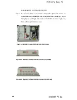
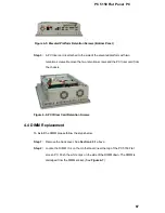
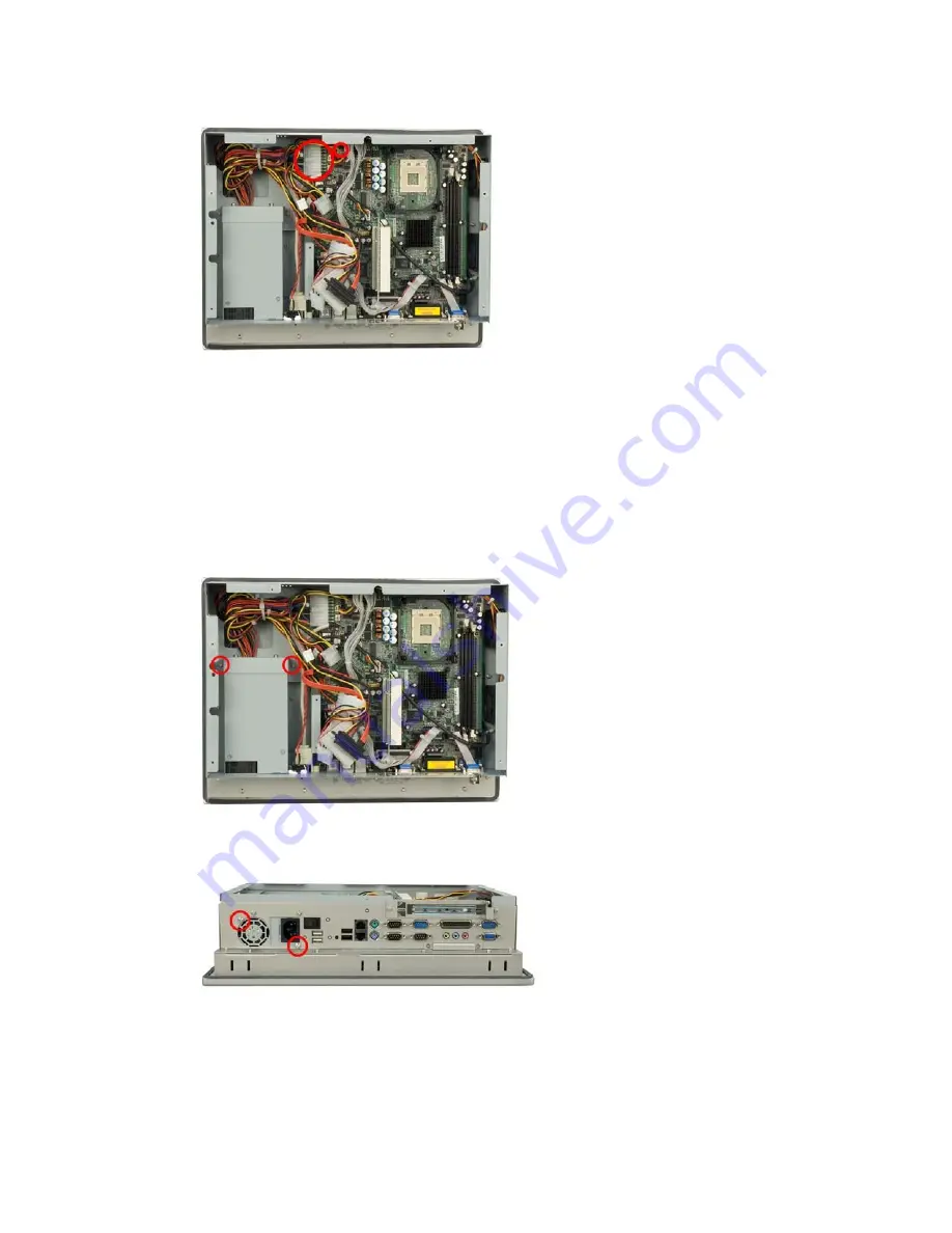
Figure 4-8: PSU Motherboard Connector
Step 5:
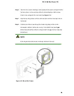
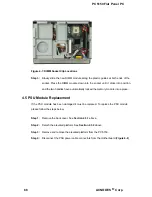
The PSU module is secured to the PC 5150 Flat panel PC with four retention
screws, two connect to the metal sheet at the back of the 15”TFT LCD screen
(
Figure 4-9
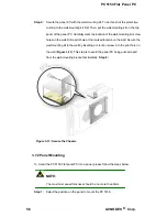
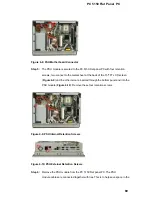
) and the other two are inserted through the bottom panel and into the
PSU module (
Figure 4-10
). Remove these four retention screws.
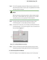
Figure 4-9: PSU Internal Retention Screws
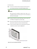
Figure 4-10: PSU External Retention Screws
Step 6:
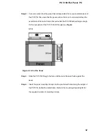
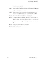
Remove the PSU module from the PC 5150 Flat panel PC. The PSU
module cables are connected together with ties. This is to help save space in the
69
Summary of Contents for PC 5150
Page 1: ...PC 5150 Flat Panel PC USEER MANUAL...
Page 2: ...1...
Page 13: ...12 ACNODES Corp...
Page 18: ...PC 5150 Flat Panel PC Chapter 1 1 Introduction 17...
Page 30: ...PC 5150 Flat Panel PC Figure 1 8 Dimensions units in mm 29...
Page 31: ...PC 5150 Flat Panel PC THIS PAGE IS INTENTIONALLY LEFT BLANK 30 ACNODES Corp...
Page 32: ...PC 5150 Flat Panel PC Chapter 2 2EMBEDED Motherboard 31...
Page 39: ...PC 5150 Flat Panel PC THIS PAGE IS INTENTIONALLY LEFT BLANK 38 ACNODES Corp...
Page 40: ...PC 5150 Flat Panel PC Chapter 3 3 Installation and Configuration 39...
Page 44: ...42 ACNODES Corp...
Page 65: ...PC 5150 Flat Panel PC Chapter 4 4 System Maintenance 63...
Page 73: ...PC 5150 Flat Panel PC Chapter 5 5 AMI BIOS 71...
Page 127: ...PC 5150 Flat Panel PC Appendix A A Interface Connectors 125...
Page 139: ...ACNO DES Corp...
Page 145: ...PC 5150 Flat Panel PC THIS PAGE IS INTENTIONALLY LEFT BLANK 142 ACNODES Corp...
Page 146: ...PC 5150 Flat Panel PC Appendix B B BIOS Configuration Options 143...
Page 151: ...PC 5150 Flat Panel PC THIS PAGE IS INTENTIONALLY LEFT BLANK 148 ACNODES Corp...
Page 152: ...PC 5150 Flat Panel PC Appendix C C Software Drivers 149...
Page 161: ...PC 5150 Flat Panel PC THIS PAGE IS INTENTIONALLY LEFT BLANK 158 ACNODES Corp...
Page 162: ...PC 5150 Flat Panel PC E Index 159...

