Chapter 1 Introduction
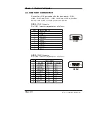
COM1/2/3/4 contain 5V or 12V power capability with 9-pin D-sub
connector on rear panel. COM4 with 9-pin box-header available for
touch panel installed.
z
PARALLEL PORT :
One 25-pin D-Sub connector on rear panel.
Support for SPP, ECP, EPP Function.
Bi-directional parallel port.
z
LAN ADAPTER :
Intel® 82541 chip.
RJ-45 jack onboard, Support for 10/100/1000 mbps Ethernet.
Support Wake-On-LAN function.
z
USB CONNECTOR :
Two USB ports on rear panel.
One internal USB port for touch panel.
Complies with USB Spec Rev 2.0.
z
SOUND :
RealTek ALC202A , AC’ 97 Codec. The signal of MIC-in, Line-in, Line-
out connectors on rear panel and CD audio-in designed in as a standard
connector.
z
HARDWARE MONITORING FUNCTION :
Monitor CPU Voltage, CPU Temperature and Cooling Fan.
z
LED INDICATOR :
System power.
HDD Read/write.
z
DMA CONTROLLER :
82C37 x 2
z
DMA CHANNELS :
7
z
INTERRUPT CONTROLLERS :
82C59 x 2
!
Page: 1-6
PC 5171 USER
c
S MANUAL
Summary of Contents for PC 5171
Page 1: ...USER S MANUAL PC 5171 Socket 478 P4 P4 M 17 inch Panel PC System...
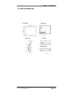
Page 9: ...Chapter 1 Introduction 1 2 CASE ILLUSTRATION PC 5171 USERc MANUAL Page 1 3...
Page 96: ...Appendix A System Assembly Diagram 2 PC 5171 USERcS MANUAL Page A 7...
Page 98: ...Appendix A System Assembly Diagram 2 PC 5171 USERcS MANUAL Page A 9...
Page 104: ...Appendix A System Assembly Diagram 2 Remove CD ROM PC 5171 USERcS MANUAL Page A 15...
Page 105: ...Appendix A System Assembly EXPLODED DIAGRAM FOR REMOVING MASK Page A 16 PC 5171 USERcS MANUAL...
Page 107: ...Appendix A System Assembly Diagram 2 Page A 18 PC 5171 USERcS MANUAL...
Page 108: ...Appendix A System Assembly Diagram 3 Diagram 4 PC 5171 USERcS MANUAL Page A 19...
Page 110: ...Appendix B Technical Summary BLOCK DIAGRAM Page B 2 PC 5171 USERcS MANUAL...

