Chapter 1 Introduction
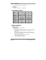
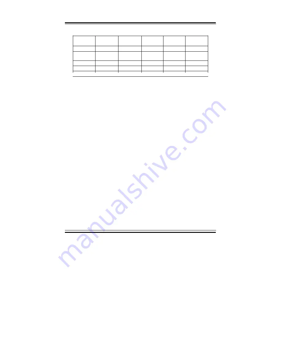
Output Requirements:
!
Njojnvn!
Mpbe!
Nbyjnvn!
Mpbe!
Mpbe!Sfr/
Mjof!Sfh/
Sjqqmf!'!
Opjtf!
,4/4W!
1/4B!
27/9B!
²6&!
²2&!
61nW!Q.Q!
,6W!
1/4B!
23B!
²6&!
²2&!
61nW!Q.Q!
,23W!
2/6B!
21B!
²6&!
²2&!
!
.23W!
1/1B!
1/9B!
²21&!
²2&!
!
,6Wtc!
1/1B!
3/1B!
²6&!
²2&!
61nW!Q.Q!
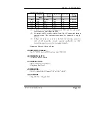
(1) +3.3V & +5V total output shall not exceed 70W, and the total output
for this subject power supply is 200W.
(2) All outputs shall be safety-isolated from the AC mains and share a
common return. This common return must be connected to supply
chassis.
(3) Voltages and ripple are measured at the load side of mating connectors
with a 0.1uF monolithic ceramic capacitor paralleled by a 10uF
electrolytic capacitor across the measuring terminals.
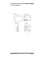
Dimension: 80mm x 130mm x 40mm
z
DRIVE BAYS (Optional) :
One 3.5” HDD, one slim FDD, and one slim CD-ROM
z
EXPANSION SLOTS :
PCI slot for Riser Card use.
z
CONSTRUCTION :
Electo Galvanized steel chassis.
Aluminium front bezel.
z
DIMENSIONS :
PC 5171: 440 x 344 x 123mm (17.32” x 13.54” x 4.85”)
z
NET WEIGHT :
9.5kg (20.9lb) ~ 11kg (24.2lb)
!
PC 5171 USER
c
S MANUAL
Page: 1-9
Summary of Contents for PC 5171
Page 1: ...USER S MANUAL PC 5171 Socket 478 P4 P4 M 17 inch Panel PC System...
Page 9: ...Chapter 1 Introduction 1 2 CASE ILLUSTRATION PC 5171 USERc MANUAL Page 1 3...
Page 96: ...Appendix A System Assembly Diagram 2 PC 5171 USERcS MANUAL Page A 7...
Page 98: ...Appendix A System Assembly Diagram 2 PC 5171 USERcS MANUAL Page A 9...
Page 104: ...Appendix A System Assembly Diagram 2 Remove CD ROM PC 5171 USERcS MANUAL Page A 15...
Page 105: ...Appendix A System Assembly EXPLODED DIAGRAM FOR REMOVING MASK Page A 16 PC 5171 USERcS MANUAL...
Page 107: ...Appendix A System Assembly Diagram 2 Page A 18 PC 5171 USERcS MANUAL...
Page 108: ...Appendix A System Assembly Diagram 3 Diagram 4 PC 5171 USERcS MANUAL Page A 19...
Page 110: ...Appendix B Technical Summary BLOCK DIAGRAM Page B 2 PC 5171 USERcS MANUAL...

