Chapter 2 Hardware Configuration
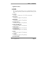
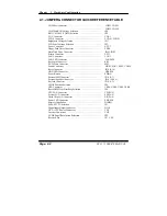
2-1. JUMPER & CONNECTOR QUICK REFERENCE TABLE
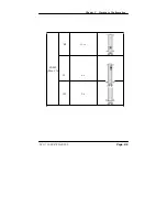
COM Port Connector ……………………………………....
………………………………………
COM1, COM2
COM3, COM4
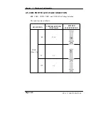
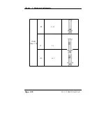
COM Port RI & Voltage Selection ………………………
JP8
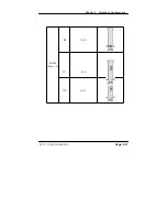
RS232/422/485 (COM2) Selection .....................………….
JP9
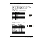
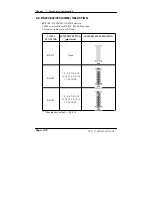
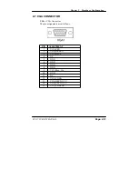
VGA Connector ……………………………………………
VGA1
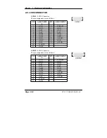
LVDS Connector ...............................................…………..
LVDS1, LVDS2
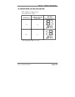
Brightness Voltage Selection ………………………..……..
JP11
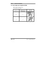
LCD Panel Voltage Selection ……………………………..
JP3
Power Connector ………………………………………….
ATX1
Floppy Disk Drive Connector …..........................………… FDD1
Hard Disk Drive Connector ….............................………… IDE1,
IDE2
Printer Connector ………………………………………….
LPT1
LAN Connector ….......................…....................…………
LAN1
LAN LED Connector ……………………………………… LANLED1
Keyboard Connector ………………………………………
KB1
PS/2 Mouse Connector ……...........................…………….
MS1
Sound Connector …………………………………………..
LINE1, MIC1, SPK1, CDIN1
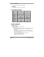
Reset Connector …............................................…………..
JP10 (9-10)
HDD LED Connector ……………………………………..
HDLED1
Power Button …………………….………………………..
PWBN
External SMI Connector ………………………………….
JP10 (5-7)
External Speaker Connector ……………………………..
JP10 (2,4,6,8)
Keylock Connector ……………………………………….
JP10 (1,3)
CMOS Function Selection …………………………………
JP4
USB Connector ……………………………………………
USB1, USB2, USB3, USB4
Reset/NMI/Clear Watchdog Selection ……….……………
JP6
CPU FAN Connector ………………………………………
CPUFAN
System FAN Connector …………………………………..
SYSFAN
North Chip FAN Connector ………………………………
NB_FAN
Power LED Connector …………………………………….
PWLED1
Memory Installation ……..................................…..………
DIMM1
P4/P4-M CPU Selection ………………………………….
JP1
Digital Input/Output Connector …………………………..
DIO1
ATX +12V Power Connector ………………………….
CN1
Inverter Connector …………………………………….
CN2
LVDS Panel Resolution Selection …………………….
JP2
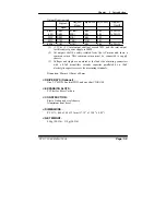
Reserved Pin ………………………………………………
JP7, CN3
Page: 2-2
PC 5171 USER
’
S MANUAL
Summary of Contents for PC 5171
Page 1: ...USER S MANUAL PC 5171 Socket 478 P4 P4 M 17 inch Panel PC System...
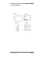
Page 9: ...Chapter 1 Introduction 1 2 CASE ILLUSTRATION PC 5171 USERc MANUAL Page 1 3...
Page 96: ...Appendix A System Assembly Diagram 2 PC 5171 USERcS MANUAL Page A 7...
Page 98: ...Appendix A System Assembly Diagram 2 PC 5171 USERcS MANUAL Page A 9...
Page 104: ...Appendix A System Assembly Diagram 2 Remove CD ROM PC 5171 USERcS MANUAL Page A 15...
Page 105: ...Appendix A System Assembly EXPLODED DIAGRAM FOR REMOVING MASK Page A 16 PC 5171 USERcS MANUAL...
Page 107: ...Appendix A System Assembly Diagram 2 Page A 18 PC 5171 USERcS MANUAL...
Page 108: ...Appendix A System Assembly Diagram 3 Diagram 4 PC 5171 USERcS MANUAL Page A 19...
Page 110: ...Appendix B Technical Summary BLOCK DIAGRAM Page B 2 PC 5171 USERcS MANUAL...

