Contents
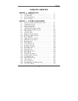
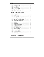
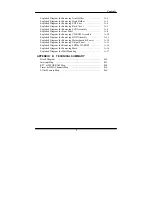
TABLE OF CONTENTS
CHAPTER 1 INTRODUCTION
1-1 About This Manual .......................................................
1-2
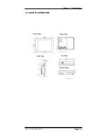
1-2 Case Illustration .............................................................
1-3
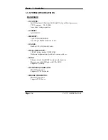
1-3 System Specification .....................................................
1-4
1-4 Safety Precautions ......................................................... 1-9
CHAPTER 2 SYSTEM CONFIGURATION
2-1 Jumper & Connector Quick Reference Table ...............
2-2
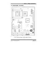
2-2 Component Locations ...................................................
2-3
2-3 How to Set the Jumpers ................................................
2-4
2-4 COM Port Connector …………………………………
2-6
2-5 COM Port RI & Voltage Selection ……………….…..
2-8
2-6 RS232/422/485 (COM2) Selection …………..….……
2-12
2-7 VGA Connector ………………………………………..
2-13
2-8 LVDS Connector ………………………………………
2-14
2-9 Brightness Voltage Selection ………………………….
2-15
2-10 LCD Panel Voltage Selection …………………………
2-16
2-11 Power Connector ………………………………………. 2-17
2-12 Floppy Disk Drive Connector …………………………
2-18
2-13 Hard Disk Drive Connector ………..………………….
2-19
2-14 Printer Connector ……………………………………… 2-21
2-15 LAN Connector ………………….…………………….
2-22
2-16 LAN LED Connector …...……………………………..
2-22
2-17 Keyboard Connector …………………………………..
2-23
2-18 PS/2 Mouse Connector ………………………………… 2-23
2-19 Sound Connector ………………………………………. 2-24
2-20 Reset Connector ……………………………………….. 2-25
2-21 HDD LED Connector ………………………………….. 2-25
2-22 Power Button ………………….….................................
2-26
2-23 External SMI Connector ……………………………….
2-26
2-24 External Speaker Connector …………………………… 2-26
2-25 Keylock Connector …………………………………….
2-27
2-26 Clear CMOS Selection ………………………………… 2-27
2-27 USB Connector ………………………………………..
2-28
2-28 Inverter Connector …………………………………….. 2-29
2-29 Reset/NMI/Clear Watchdog Selection ………………… 2-30
2-30 CPU FAN Connector ………………………………….. 2-31
!
Summary of Contents for PC 5171
Page 1: ...USER S MANUAL PC 5171 Socket 478 P4 P4 M 17 inch Panel PC System...
Page 9: ...Chapter 1 Introduction 1 2 CASE ILLUSTRATION PC 5171 USERc MANUAL Page 1 3...
Page 96: ...Appendix A System Assembly Diagram 2 PC 5171 USERcS MANUAL Page A 7...
Page 98: ...Appendix A System Assembly Diagram 2 PC 5171 USERcS MANUAL Page A 9...
Page 104: ...Appendix A System Assembly Diagram 2 Remove CD ROM PC 5171 USERcS MANUAL Page A 15...
Page 105: ...Appendix A System Assembly EXPLODED DIAGRAM FOR REMOVING MASK Page A 16 PC 5171 USERcS MANUAL...
Page 107: ...Appendix A System Assembly Diagram 2 Page A 18 PC 5171 USERcS MANUAL...
Page 108: ...Appendix A System Assembly Diagram 3 Diagram 4 PC 5171 USERcS MANUAL Page A 19...
Page 110: ...Appendix B Technical Summary BLOCK DIAGRAM Page B 2 PC 5171 USERcS MANUAL...

