Chapter 2 Hardware Configuration
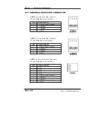
2-19. SOUND CONNECTOR
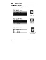
The sound connector is composed of the Microphone (MIC1), Line-Out
(LINE_OUT), Line-In (LINE_IN) and CDIN connector.
LINE1 :
Line-In Connector
The pin assignment is as follows :
PIN ASSIGNMENT
1 GND
2 LINE_L
3 LINE_R
MIC1 :
Microphone Connector
The pin assignment is as follows :
PIN ASSIGNMENT
1 GND
2 MIC-IN
3 MIC VDD
SPK1 :
Line-Out Connector
The pin assignment is as follows :
PIN ASSIGNMENT
1 GND
2 Line-Out-L
3 Line-Out-R
Page: 2-24
PC 5171 USER
’
S MANUAL
Summary of Contents for PC 5171
Page 1: ...USER S MANUAL PC 5171 Socket 478 P4 P4 M 17 inch Panel PC System...
Page 9: ...Chapter 1 Introduction 1 2 CASE ILLUSTRATION PC 5171 USERc MANUAL Page 1 3...
Page 96: ...Appendix A System Assembly Diagram 2 PC 5171 USERcS MANUAL Page A 7...
Page 98: ...Appendix A System Assembly Diagram 2 PC 5171 USERcS MANUAL Page A 9...
Page 104: ...Appendix A System Assembly Diagram 2 Remove CD ROM PC 5171 USERcS MANUAL Page A 15...
Page 105: ...Appendix A System Assembly EXPLODED DIAGRAM FOR REMOVING MASK Page A 16 PC 5171 USERcS MANUAL...
Page 107: ...Appendix A System Assembly Diagram 2 Page A 18 PC 5171 USERcS MANUAL...
Page 108: ...Appendix A System Assembly Diagram 3 Diagram 4 PC 5171 USERcS MANUAL Page A 19...
Page 110: ...Appendix B Technical Summary BLOCK DIAGRAM Page B 2 PC 5171 USERcS MANUAL...

