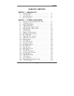
Contents
2-31 System FAN Connector ………………………………..
2-31
2-32 North Chip FAN Connector …………………………… 2-31
2-33 Power LED Connector ………………………………… 2-32
2-34 Memory Installation ............………..............................
2-32
2-35 P4/ P4-M CPU Selection ………………………………
2-33
2-36 Digital Input/Output Connector ………………………..
2-34
2-37 ATX +12V Power Connector ………………………….
2-34
2-38 LVDS Panel Resolution Selection …………………….. 2-35
CHAPTER 3 SOFTWARE UTILITIES
3-1 Introduction ...................................................................
3-2
3-2 VGA Driver Utility ....................................................... 3-3
3-3 Flash BIOS Update .......................................................
3-4
3-4 LAN Driver Utility ........................................................ 3-6
3-5 Sound Driver Utility .............................…...................... 3-7
3-6 Intel® Chipset Software Installation Utility …………
3-8
3-7 USB2.0 Chipset Software Installation Utility …………. 3-9
3-8 Touch Screen Driver Utility (Optional) ………..……..
3-9
3-9 USB CF Card Driver Utility (Optional) ………………
3-9
3-10 Watchdog Timer Configuration .................................... 3-10
CHAPTER 4 AWARD BIOS SETUP
4-1 Introduction ...................................................................
4-2
4-2 Entering Setup ...............................................................
4-3
4-3 The Standard CMOS Features …..................................
4-4
4-4 The Advance BIOS Features …....................................
4-8
4-5 The Advanced Chipset Features ...................................
4-11
4-6 Integrated Peripherals ……...........................................
4-14
4-7 Power Management Setup …………………………….
4-18
4-8 PNP/PCI Configuration ................................................
4-20
4-9 PC Health Status ……………………………………..
4-22
4-10 Frequency / Voltage Control …………………………
4-24
4-11 Load Fail-Safe Defaults ................................................
4-25
4-12 Load Optimized Defaults ..............................................
4-25
4-13 Password Setting .................................................…...... 4-26
4-14 Save & Exit Setup .........................................................
4-27
4-15 Exit Without Saving ......................................................
4-28
!
APPENDIX A SYSTEM ASSEMBLY
!
Summary of Contents for PC 5171
Page 1: ...USER S MANUAL PC 5171 Socket 478 P4 P4 M 17 inch Panel PC System...
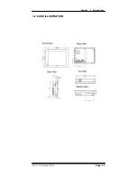
Page 9: ...Chapter 1 Introduction 1 2 CASE ILLUSTRATION PC 5171 USERc MANUAL Page 1 3...
Page 96: ...Appendix A System Assembly Diagram 2 PC 5171 USERcS MANUAL Page A 7...
Page 98: ...Appendix A System Assembly Diagram 2 PC 5171 USERcS MANUAL Page A 9...
Page 104: ...Appendix A System Assembly Diagram 2 Remove CD ROM PC 5171 USERcS MANUAL Page A 15...
Page 105: ...Appendix A System Assembly EXPLODED DIAGRAM FOR REMOVING MASK Page A 16 PC 5171 USERcS MANUAL...
Page 107: ...Appendix A System Assembly Diagram 2 Page A 18 PC 5171 USERcS MANUAL...
Page 108: ...Appendix A System Assembly Diagram 3 Diagram 4 PC 5171 USERcS MANUAL Page A 19...
Page 110: ...Appendix B Technical Summary BLOCK DIAGRAM Page B 2 PC 5171 USERcS MANUAL...

