Chapter 3 Software Configuration
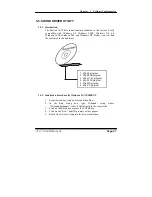
3-3. FLASH BIOS UPDATE
3-3-1. System BIOS Update:
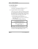
Users of PC 5171 can use the program “Awdflash.exe” contained in
the Utility Disk for system BIOS and VGA BIOS update.
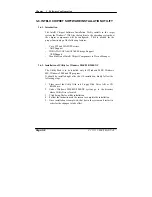
3-3-2. To update VGA BIOS for LCD Flat Panel Display:
As PC 5171 user, you have to update the VGA BIOS for your specific
LCD flat panel you are going to use. For doing this, you need two files.
One is the “Awdflash.exe” file and the other is the VGA BIOS for ATI
Rage Mobility M6 file for LCD panel display. Both file must be
provided by the vendor or manufacturer. When you get these two files
ready, follow the following steps for updating your VGA BIOS:
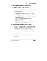
1. Install “Awdflash.exe” from Utility Disk to Drive C.
2. Insert the VGA BIOS file you have obtained from the vendor.
Type the path to Awdflash.exe and execute the VGA BIOS update
with file H15bxxxx.bin
3. C:\UTIL\AWDFLASH>AWDFLASH H15bxxxx.bin
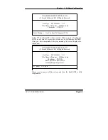
4. The screen will display as the table fount on the next page:
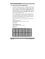
FLASH MEMORY WRITER v8.XX
(C) Award Software 2001 All Rights Reserved
Flash Type – SST 49LF004A /3.3V
File Name to Program:
H20bxxxx.bin
Checksum: XXXXX
Error Message: Do You Want To Save BIOS (Y/N)
If you want to save up the original BIOS, enter
"
Y
"
and press < Enter >.
If you choose
"
N
"
, the following table will appear on screen.
Page:3-4
PC 5171 USER
′
S MANUAL
Summary of Contents for PC 5171
Page 1: ...USER S MANUAL PC 5171 Socket 478 P4 P4 M 17 inch Panel PC System...
Page 9: ...Chapter 1 Introduction 1 2 CASE ILLUSTRATION PC 5171 USERc MANUAL Page 1 3...
Page 96: ...Appendix A System Assembly Diagram 2 PC 5171 USERcS MANUAL Page A 7...
Page 98: ...Appendix A System Assembly Diagram 2 PC 5171 USERcS MANUAL Page A 9...
Page 104: ...Appendix A System Assembly Diagram 2 Remove CD ROM PC 5171 USERcS MANUAL Page A 15...
Page 105: ...Appendix A System Assembly EXPLODED DIAGRAM FOR REMOVING MASK Page A 16 PC 5171 USERcS MANUAL...
Page 107: ...Appendix A System Assembly Diagram 2 Page A 18 PC 5171 USERcS MANUAL...
Page 108: ...Appendix A System Assembly Diagram 3 Diagram 4 PC 5171 USERcS MANUAL Page A 19...
Page 110: ...Appendix B Technical Summary BLOCK DIAGRAM Page B 2 PC 5171 USERcS MANUAL...

