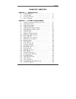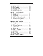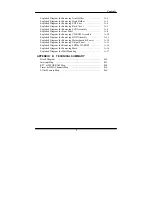
Contents
Exploded Diagram for Removing Arm Holder ………………
A-2
Exploded Diagram for Removing Hook Holder ……………… A-3
Exploded Diagram for Removing EXT-Case …………………
A-4
Exploded Diagram for Removing Back Cover ………………..
A-5
Exploded Diagram for Removing LCD Assembly ………….
A-6
Exploded Diagram for Front Panel ……………………………
A-8
Exploded Diagram for Removing CD-ROM Assembly ………
A-10
Exploded Diagram for Removing HDD Assembly …………… A-11
Exploded Diagram for Removing Motherboard & Power ……
A-12
Exploded Diagram for Removing Output Panel ………………
A-13
Exploded Diagram for Removing FDD & CD-ROM ………… A-14
Exploded Diagram for Removing Mask ………………………. A-16
Exploded Diagram for Wall Mounting ………………………..
A-17
APPENDIX B TECHNICAL SUMMARY
Block Diagram .........................................................................
B-2
Interrupt Map ............................................................................
B-3
RTC & CMOS RAM Map .......................................................
B-4
Timer & DMA Channels Map ..................................................
B-5
I/O & Memory Map .................................................................
B-6
!
Summary of Contents for PC 5171
Page 1: ...USER S MANUAL PC 5171 Socket 478 P4 P4 M 17 inch Panel PC System...
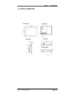
Page 9: ...Chapter 1 Introduction 1 2 CASE ILLUSTRATION PC 5171 USERc MANUAL Page 1 3...
Page 96: ...Appendix A System Assembly Diagram 2 PC 5171 USERcS MANUAL Page A 7...
Page 98: ...Appendix A System Assembly Diagram 2 PC 5171 USERcS MANUAL Page A 9...
Page 104: ...Appendix A System Assembly Diagram 2 Remove CD ROM PC 5171 USERcS MANUAL Page A 15...
Page 105: ...Appendix A System Assembly EXPLODED DIAGRAM FOR REMOVING MASK Page A 16 PC 5171 USERcS MANUAL...
Page 107: ...Appendix A System Assembly Diagram 2 Page A 18 PC 5171 USERcS MANUAL...
Page 108: ...Appendix A System Assembly Diagram 3 Diagram 4 PC 5171 USERcS MANUAL Page A 19...
Page 110: ...Appendix B Technical Summary BLOCK DIAGRAM Page B 2 PC 5171 USERcS MANUAL...

