Chapter 3 Software Configuration
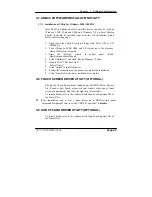
3-7. USB2.0 SOFTWARE INSTALLATION UTILITY
3-7-1. Installation of Utility for Windows 98SE/ 2000/XP
Intel USB 2.0 Enhanced Host Controller driver can only be used on
Windows 98SE, Windows 2000 and Windows XP on Intel Desktop
boards. It should be installed right after the OS installation, kindly
follow the following steps:
1. Place insert the Utility Disk into Floppy Disk Drive A/B or CD
ROM drive.
2. Under Windows 98SE, 2000, and XP system, go to the directory
where Utility Disc is located.
3. Start the
“System”
wizard in control panel. (Click
Start/Settings/Control Panel).
4. Select “Hardware” and click “Device Manager ” button.
5. Double Click “USB Root Hub”.
6. Select “Driver”.
7. Click “Install” to install the driver.
8. Follow the instructions on the screen to complete the installation.
9. Click “Finish” after the driver installation is complete.
3-8. TOUCH SCREEN DRIVER UTILITY (OPTIONAL)
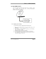
The type of Touch Screen driver found on our CD-ROM Driver Disc are
Liyi Touch or Fuji Touch, please ask your vendor, what type of touch
screen you purchased, and select the right driver to install it.
To install, kindly refer to the readme.txt file found each separate file of
the Driver Disc.
If the installation time is over 1 hour, please go to BIOS setting, under
“Integrated Peripherals” item to set the “USB2.0 Controller” to
disable
.
3-9. USB CF CARD DRIVER UTILITY (OPTIONAL)
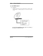
To install, kindly refer to the readme.txt file found each separate file of
the Driver Disc.
PC 5171 USER
′
S MANUAL
Page:3-9
Summary of Contents for PC 5171
Page 1: ...USER S MANUAL PC 5171 Socket 478 P4 P4 M 17 inch Panel PC System...
Page 9: ...Chapter 1 Introduction 1 2 CASE ILLUSTRATION PC 5171 USERc MANUAL Page 1 3...
Page 96: ...Appendix A System Assembly Diagram 2 PC 5171 USERcS MANUAL Page A 7...
Page 98: ...Appendix A System Assembly Diagram 2 PC 5171 USERcS MANUAL Page A 9...
Page 104: ...Appendix A System Assembly Diagram 2 Remove CD ROM PC 5171 USERcS MANUAL Page A 15...
Page 105: ...Appendix A System Assembly EXPLODED DIAGRAM FOR REMOVING MASK Page A 16 PC 5171 USERcS MANUAL...
Page 107: ...Appendix A System Assembly Diagram 2 Page A 18 PC 5171 USERcS MANUAL...
Page 108: ...Appendix A System Assembly Diagram 3 Diagram 4 PC 5171 USERcS MANUAL Page A 19...
Page 110: ...Appendix B Technical Summary BLOCK DIAGRAM Page B 2 PC 5171 USERcS MANUAL...

