Chapter 4 Award BIOS Setup
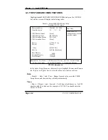
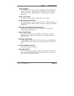
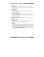
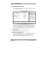
VIRUS WARNING :
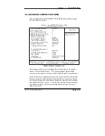
This item allows you to choose the Virus Warning feature for IDE Hard Disk
boot sector protection. If this function is enabled and someone attempt to
write data into this area, BIOS will show a warning message on screen and
alarm beep.
CPU L1 & L2 CACHE :
This item allows you to enable or disable CPU L1 & L2 Cache.
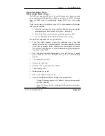
QUICK POWER ON SELF-TEST:
This item allows you to speed up Power On Self Test (POST) after power-up
the computer. When enabled, the BIOS will shorten or skip some check items
during POST.
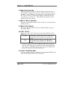
FIRST/SECOND/THIRD/OTHER BOOT DEVICE:
The BIOS attempt to load the operating system from the devices in the
sequence selected in these items.
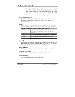
SWAP FLOOPY DRIVE:
This field is effective only in systems with two floppy drives. Selecting
Enabled assigns physical drive B to logical drive A, and physical drive A to
logical drive B.
BOOT UP FLOPPY SEEK:
You may enable / disable this item to define whether the system will look for
a floppy disk drive to boot at power-on, or proceed directly to the hard disk
drive.
BOOT UP NUMLOCK STATUS:
Select power on state for NumLock.
GATE 20A OPTION:
This entry allows you to select how the gate A20 is handled. When Normal
was set, a pin in the keyboard controller controls Gate A20. And when Fast
was set, the chipset controls Gate A20.
PC 5171 USER
c
S MANUAL
Page: 4-9
Summary of Contents for PC 5171
Page 1: ...USER S MANUAL PC 5171 Socket 478 P4 P4 M 17 inch Panel PC System...
Page 9: ...Chapter 1 Introduction 1 2 CASE ILLUSTRATION PC 5171 USERc MANUAL Page 1 3...
Page 96: ...Appendix A System Assembly Diagram 2 PC 5171 USERcS MANUAL Page A 7...
Page 98: ...Appendix A System Assembly Diagram 2 PC 5171 USERcS MANUAL Page A 9...
Page 104: ...Appendix A System Assembly Diagram 2 Remove CD ROM PC 5171 USERcS MANUAL Page A 15...
Page 105: ...Appendix A System Assembly EXPLODED DIAGRAM FOR REMOVING MASK Page A 16 PC 5171 USERcS MANUAL...
Page 107: ...Appendix A System Assembly Diagram 2 Page A 18 PC 5171 USERcS MANUAL...
Page 108: ...Appendix A System Assembly Diagram 3 Diagram 4 PC 5171 USERcS MANUAL Page A 19...
Page 110: ...Appendix B Technical Summary BLOCK DIAGRAM Page B 2 PC 5171 USERcS MANUAL...

