Chapter 4 Award BIOS Setup
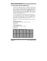
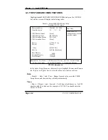
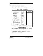
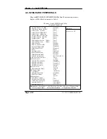
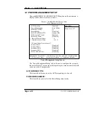
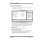
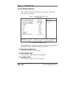
4-6. INTEGRATED PERIPHERALS
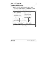
Choose
ň
INTEGRATED PERIPHERALS
ʼn
from the main setup menu, a
display will be shown on screen as below:
Phoenix – Award CMOS Setup Utility
Integrated Peripherals
On-Chip Primary PCI IDE
IDE Primary Master PIO IDE
Primary Slave PIO IDE
Primary Master UDMA IDE
Primary Slave UDMA On-
Chip Secondary PCI IDE IDE
Secondary Master PIO IDE
Secondary Slave PIO
IDE Secondary Master UDMA
IDE Secondary Slave UDMA
USB Controller
USB 2.0 Controller USB
Keyboard Support USB
Mouse Support AC97
Audio
Init Display First
BIOS Flash Function
IDE HDD Block Mode
POWER ON Function
x KB Power ON Password x
Hot Key Power ON
Onboard FDC Controller
Onboard Serial Port 1
Onboard Serial Port 2
UART Mode Select x
RxD, TxD Active
x IR Transmission Delay x
UR2 Duplex Mode
x Use IR Pins
Onboard Parallel Port
Parallel Port Mode x
EPP Mode Select
x ECP Mode Use DMA
PWRON After PWR-Fail
Watch Dog Timer Select
Onboard Serial Port 3
Onboard Serial Port 4
[Enabled]
[Auto]
[Auto]
[Auto]
[Auto]
[Enabled]
[Auto]
[Auto]
[Auto]
[Auto]
[Enabled]
[Enabled]
[Disabled]
[Disabled]
[Auto]
[Onboard]
[Enabled]
[Enabled]
[BUTTON ONLY]
Enter
Ctrl-F1
[Enabled]
[3F8/IRQ4]
[2F8/IRQ3]
[Normal]
Hi, Lo
Enabled
Half
IR-Rx2Tx2
[378/IRQ7]
[SPP]
EPP1.7
3
[Off]
[Disabled]
[3E8/ IRQ10]
[2E8/ IRQ11]
Item Help
Menu Level
Ź
npom
:Move Enter: Select +/-/PU/PD:Value F10:Save ESC:Exit F1:General Help
F5: Previous Values F6:Fail-Safe Defaults F7:Optimized Defaults
Page: 4-14
PC 5171 USER
c
S MANUAL
Summary of Contents for PC 5171
Page 1: ...USER S MANUAL PC 5171 Socket 478 P4 P4 M 17 inch Panel PC System...
Page 9: ...Chapter 1 Introduction 1 2 CASE ILLUSTRATION PC 5171 USERc MANUAL Page 1 3...
Page 96: ...Appendix A System Assembly Diagram 2 PC 5171 USERcS MANUAL Page A 7...
Page 98: ...Appendix A System Assembly Diagram 2 PC 5171 USERcS MANUAL Page A 9...
Page 104: ...Appendix A System Assembly Diagram 2 Remove CD ROM PC 5171 USERcS MANUAL Page A 15...
Page 105: ...Appendix A System Assembly EXPLODED DIAGRAM FOR REMOVING MASK Page A 16 PC 5171 USERcS MANUAL...
Page 107: ...Appendix A System Assembly Diagram 2 Page A 18 PC 5171 USERcS MANUAL...
Page 108: ...Appendix A System Assembly Diagram 3 Diagram 4 PC 5171 USERcS MANUAL Page A 19...
Page 110: ...Appendix B Technical Summary BLOCK DIAGRAM Page B 2 PC 5171 USERcS MANUAL...

