Chapter 4 Award BIOS Setup
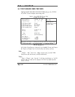
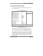
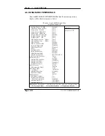
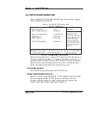
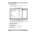
Integrated Peripherals Setup Screen
By moving the cursor to the desired selection and by pressing the <F1> key,
the all options for the desired selection will be displayed for choice.
ON-CHIP PRIMARY PCI IDE:
ON-CHIP SECONDARY PCI IDE:
The chipset contains a PCI IDE interface with support for two IDE
channels. Select Enabled to activate the primary or secondary IDE
interface. Select Disabled to deactivate this interface.
IDE PRIMARY MASTER/SLAVE PIO:
IDE SECONDARY MASTER/SLAVE PIO:
The four IDE PIO fields allow you to set a PIO mode (0-4) for each of the
four IDE devices that the onboard IDE interface supports. Modes 0 through
4 provide successively increased performance. In Auto mode, the system
automatically determines the best mode for each device.
IDE PRIMARY MASTER/SLAVE UDMA:
IDE SECONDARY MASTER/SLAVE UDMA:
Ultra DMA/33 implementation is possible only if your IDE hard drive
supports it and the operating environment includes a DMA driver (Windows
95 OSR2 or a third-party IDE bus master driver). If you hard drive and your
system software both support Ultra DMA/33, select Auto to enable BIOS
support.
USB CONTROLLER:
Select enabled if the system contains a Universal Serial Bus (USB) controller
and you have a USB peripherals.
USB KEYBOARD SUPPORT:
Select Enabled if you have a USB Keyboard.
USB MOUSE SUPPORT:
Select enabled if the system contains a Universal Serial Bus (USB) controller
and you have a USB Mouse.
AC97 Audio:
This item allows you to enable/disable to support AC97 Audio.
PC 5171 USER
c
S MANUAL
Page: 4-15
Summary of Contents for PC 5171
Page 1: ...USER S MANUAL PC 5171 Socket 478 P4 P4 M 17 inch Panel PC System...
Page 9: ...Chapter 1 Introduction 1 2 CASE ILLUSTRATION PC 5171 USERc MANUAL Page 1 3...
Page 96: ...Appendix A System Assembly Diagram 2 PC 5171 USERcS MANUAL Page A 7...
Page 98: ...Appendix A System Assembly Diagram 2 PC 5171 USERcS MANUAL Page A 9...
Page 104: ...Appendix A System Assembly Diagram 2 Remove CD ROM PC 5171 USERcS MANUAL Page A 15...
Page 105: ...Appendix A System Assembly EXPLODED DIAGRAM FOR REMOVING MASK Page A 16 PC 5171 USERcS MANUAL...
Page 107: ...Appendix A System Assembly Diagram 2 Page A 18 PC 5171 USERcS MANUAL...
Page 108: ...Appendix A System Assembly Diagram 3 Diagram 4 PC 5171 USERcS MANUAL Page A 19...
Page 110: ...Appendix B Technical Summary BLOCK DIAGRAM Page B 2 PC 5171 USERcS MANUAL...

