Chapter 4 Award BIOS Setup
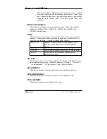
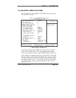
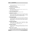
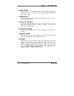
RxD, TxD ACTIVE:
This item allows you to determine the active of RxD, TxD.
IR TRANSMISSION DELAY:
This item allows you to enable/disable IR transmission delay.
UR2 DUPLEX MODE:
This item allows you to select the IR half/full duplex function.
USE IR PINS:
This item allows you to select IR transmission routes, one is RxD2m, TxD2
(COM Port) and the other is IR-Rx2Tx2.
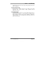
ONBOARD PARALLEL PORT:
This item allows you to determine access onboard parallel port controller with
which I/O address.
PARALLEL PORT MODE:
Select an operating mode for the onboard parallel (printer) port. Select
Normal, Compatible,
or
SPP
unless you are certain your hardware and
software both support one of the other available modes.
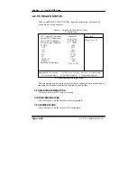
EPP MODE SELECT:
Select EPP port type 1.7 or 1.9.
ECP MODE USE DMA:
Select a DMA channel for the parallel port for use during ECP mode.
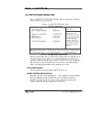
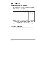
PWRON AFTER PWR-FAIL:
This item allows you to select if you want to power on the system after power
failure. The choice: Off, On, Former-Sts.
PC 5171 USER
c
S MANUAL
Page: 4-17
Summary of Contents for PC 5171
Page 1: ...USER S MANUAL PC 5171 Socket 478 P4 P4 M 17 inch Panel PC System...
Page 9: ...Chapter 1 Introduction 1 2 CASE ILLUSTRATION PC 5171 USERc MANUAL Page 1 3...
Page 96: ...Appendix A System Assembly Diagram 2 PC 5171 USERcS MANUAL Page A 7...
Page 98: ...Appendix A System Assembly Diagram 2 PC 5171 USERcS MANUAL Page A 9...
Page 104: ...Appendix A System Assembly Diagram 2 Remove CD ROM PC 5171 USERcS MANUAL Page A 15...
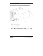
Page 105: ...Appendix A System Assembly EXPLODED DIAGRAM FOR REMOVING MASK Page A 16 PC 5171 USERcS MANUAL...
Page 107: ...Appendix A System Assembly Diagram 2 Page A 18 PC 5171 USERcS MANUAL...
Page 108: ...Appendix A System Assembly Diagram 3 Diagram 4 PC 5171 USERcS MANUAL Page A 19...
Page 110: ...Appendix B Technical Summary BLOCK DIAGRAM Page B 2 PC 5171 USERcS MANUAL...

