Chapter 4 Award BIOS Setup
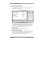
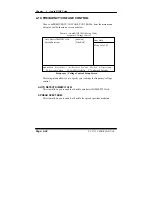
4-8. PNP/PCI CONFIGURATION
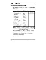
Choose
ň
PNP/PCI CONFIGURATION
ʼn
from the main menu, a display
will be shown on screen as below:
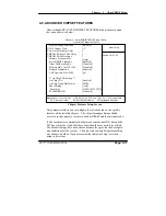
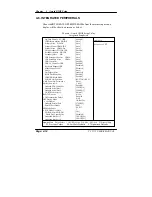
Phoenix - AwardBIOS CMOS Setup Utility
PnP/PCI Configurations
PNP OS Installed
Reset Configuration Data
Resources Controlled By
x IRQ Resources
x DMA Resources
PCI/VGA Palette Snoop
[No]
[Disabled]
[Auto(ESCD)]
Press Enter
Press Enter
[Disabled]
Item Help
Menu Level
Ź
Select Yes if you are
using a Plug and Play
capable operating
system Select No if
you need the BIOS to
configure non-boot
devices
npom
:Move Enter: Select +/-/PU/PD:Value F10:Save ESC:Exit F1:General Help
F5: Previous Values F6:Fail-Safe Defaults F7:Optimized Defaults
PNP/PCI Configuration Setup Screen
This section describes how to configure PCI bus system. PCI, also known as
Personal Computer Interconnect, is a system, which allows I/O devices to
operate at speeds nearing the speed of the CPU itself uses when communica-
ting with its own special components. This section covers technical items,
which is strongly recommended for experienced users only.
PNP OS INSTALLED:
This item allows you to determine install PnP OS or not.
RESET CONFIGURATION DATA:
Normally, you leave this field Disabled. Select Enabled to reset Extended
System Configuration Data (ESCD) when you exit Setup if you have
installed a new add-on and the system configuration has caused such a
serious conflict that the operating system cannot boot.
Page: 4-20
PC 5171 USER
c
S MANUAL
Summary of Contents for PC 5171
Page 1: ...USER S MANUAL PC 5171 Socket 478 P4 P4 M 17 inch Panel PC System...
Page 9: ...Chapter 1 Introduction 1 2 CASE ILLUSTRATION PC 5171 USERc MANUAL Page 1 3...
Page 96: ...Appendix A System Assembly Diagram 2 PC 5171 USERcS MANUAL Page A 7...
Page 98: ...Appendix A System Assembly Diagram 2 PC 5171 USERcS MANUAL Page A 9...
Page 104: ...Appendix A System Assembly Diagram 2 Remove CD ROM PC 5171 USERcS MANUAL Page A 15...
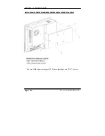
Page 105: ...Appendix A System Assembly EXPLODED DIAGRAM FOR REMOVING MASK Page A 16 PC 5171 USERcS MANUAL...
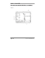
Page 107: ...Appendix A System Assembly Diagram 2 Page A 18 PC 5171 USERcS MANUAL...
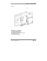
Page 108: ...Appendix A System Assembly Diagram 3 Diagram 4 PC 5171 USERcS MANUAL Page A 19...
Page 110: ...Appendix B Technical Summary BLOCK DIAGRAM Page B 2 PC 5171 USERcS MANUAL...

