54
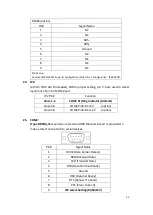
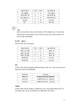
3
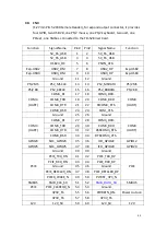
Ground
4
+5V
5
KBCLK
6
MSCLK
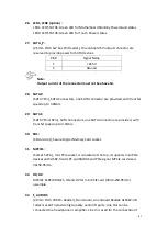
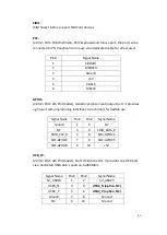
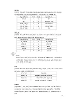
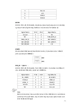
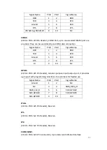
GPIO1
:
(2.0mm Pitch 2x5 Pin Header), General-purpose input/output port, it provides
a group of self-programming interfaces to customers for flexible use.
Signal Name
Pin#
Pin#
Signal Name
Ground
1
2
NC
NC
3
4
SMB_DATA_R
SMB_CLK_R
5
6
SOC-GPIO22
SOC-GPIO23
7
8
SOC-GPIO25
SOC-GPIO24
9
10
+5V
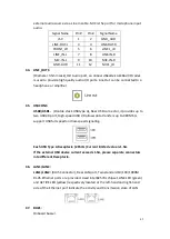
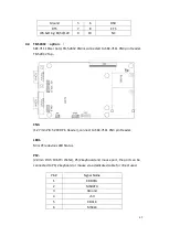
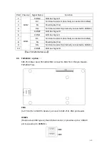
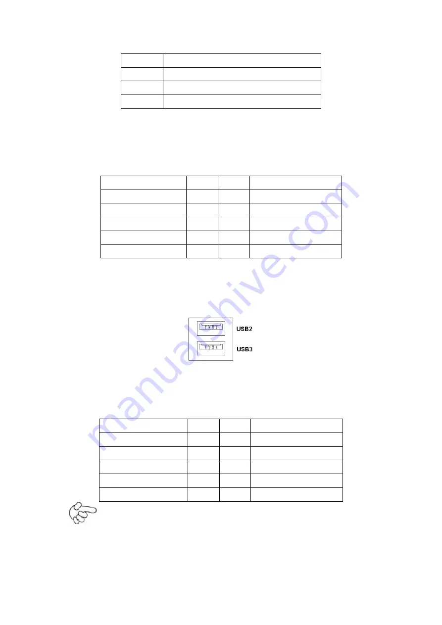
USB23
:
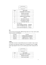
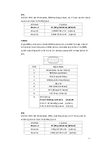
(Double stack USB type A), Rear USB connector, it provides up to 2 USB2.0
ports, speed up to 480Mb/s.
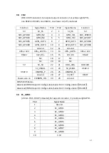
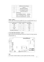
USB_23
(
option
):
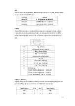
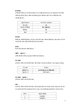
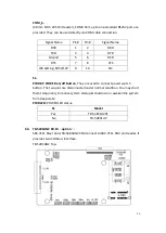
(2.0mm Pitch 2x5 Pin Header), front USB connector, it provides one USB port
via a dedicated USB cable, speed up to 480Mb/s.
Signal Name
Pin#
Pin#
Signal Name
5V_USB23
1
2
5V_USB23
USB3_N
3
4
USB2_N
USB3_P
5
6
USB2_P
Ground
7
8
Ground
NC
9
10
Ground
Note:
Before connection, make sure that pinout of the USB Cable is in accordance
with that of the said tables. Any inconformity may cause system down and
even hardware damages.
Summary of Contents for PC9 A Series
Page 12: ...11 1 3 Dimensions Figure 1 1 Dimensions of PC9070 Figure 1 2 Dimensions of PC9080...
Page 13: ...12 Figure 1 3 Dimensions of PC9101 Figure 1 4 Dimensions of PC9120...
Page 14: ...13 Figure 1 5 Dimensions of PC9150A Figure 1 6 Dimensions of PC9156A Resistive Touch...
Page 16: ...15 Figure 1 9 Dimensions of PC9185A Figure 1 10 Dimensions of PC9215A Resistive Touch...
Page 17: ...16 Figure 1 11 Dimensions of PC8215A Projected Capacitive Touch...
Page 19: ...18 Figure 1 13 Rear View of PC9170 9180 Figure 1 14 Rear View of PC9101...
Page 20: ...19 Figure 1 15 Rear View of PC9120 Figure 1 16 Rear View of PC9150A...
Page 21: ...20 Figure 1 17 Rear View of PC9156A Figure 1 18 Rear View of PC9170A...
Page 22: ...21 Figure 1 19 Rear View of PC9185A Figure 1 20 Rear View of PC9215A...
Page 32: ...31 units mm Figure 2 1 Motherboard Dimensions...
Page 83: ...82 Step 3 Read license agreement Click Yes Step 4 Click Next...
Page 84: ...83 Step 5 Click Install Step 6 Click Install...
Page 85: ...84 Step 7 Click Next Step 8 Click Yes I want to restart this computer now Then click Finish...
Page 88: ...87 Step 5 Click Install to begin the installation Step 6 Click Finish to exit the wizard...
Page 92: ...91 Step 3 Read the license agreement Then click Yes to continue Step 4 Click Next to continue...
Page 95: ...94 Step 2 Select Resistive Touch Step 3 Click Next to continue...
Page 97: ...96 Step 6 Wait for installation Then click Next to continue Step 7 Click Continue Anyway...
Page 99: ...98 Step 2 Select Projected Capacitive Step 3 Click Next to continue...
Page 102: ...101 Step 9 Go to C Program Files eGalaxTouch Click Next Step 10 Click Next...
Page 109: ...108 About This panel displays information about the PenMount controller and driver version...
Page 120: ...119 Hardware Saturn Hardware Configuration...
Page 121: ...120 About To display information about eGalaxTouch and its version...

