58
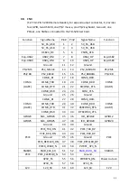
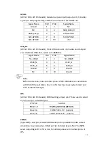
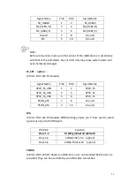
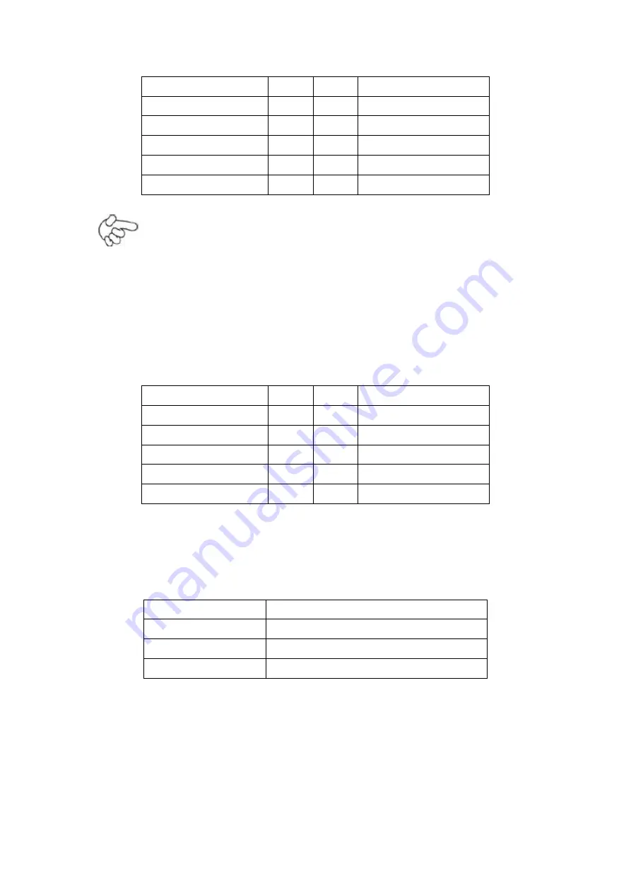
Signal Name
Pin#
Pin#
Signal Name
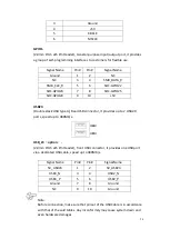
5V_USB23
1
2
5V_USB23
NC (USB3_N)
3
4
NC (USB2_N)
NC (USB3_P)
5
6
NC (USB2_P)
Ground
7
8
Ground
NC
9
10
Ground
Note:
Before connection, make sure that pinout of the USB Cable is in accordance
with that of the said tables. Any inconformity may cause system down and
even hardware damages.
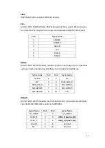
JP_SET
(
option
):
(2.0mm Pitch 2x5 Pin Header).
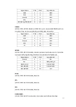
Signal Name
Pin#
Pin#
Signal Name
3P3V_S5_USB
1
2
3P3V_S5
3P3V_S5_USB
3
4
3P3V_S5
3P3V_S5_USB
5
6
3P3V_S5
PSON_ATX
7
8
Ground
PSON_ATX
9
10
Ground
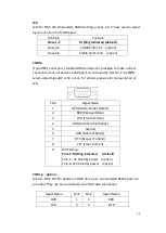
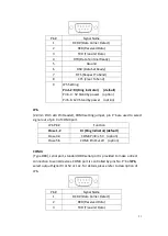
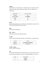
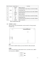
JP6
:
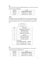
(2.0mm Pitch 2x3 Pin Header), COM4 setting jumper, pin 1~6 are used to select
signal out of pin 9 of COM4 port.
JP6 Pin#
Function
Close 1-2
RI (Ring Indicator) (default)
Close 3-4
COM4 Pin9=+5V (option)
Close 5-6
COM4 Pin9=+12V (option)
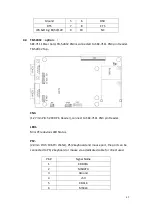
COM4
:
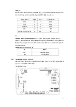
(2.0mm Pitch 2X5 Pin Header), COM4 Port, up to one standard RS232 port are
provided. They can be used directly via COM cable connection.
Summary of Contents for PC9 A Series
Page 12: ...11 1 3 Dimensions Figure 1 1 Dimensions of PC9070 Figure 1 2 Dimensions of PC9080...
Page 13: ...12 Figure 1 3 Dimensions of PC9101 Figure 1 4 Dimensions of PC9120...
Page 14: ...13 Figure 1 5 Dimensions of PC9150A Figure 1 6 Dimensions of PC9156A Resistive Touch...
Page 16: ...15 Figure 1 9 Dimensions of PC9185A Figure 1 10 Dimensions of PC9215A Resistive Touch...
Page 17: ...16 Figure 1 11 Dimensions of PC8215A Projected Capacitive Touch...
Page 19: ...18 Figure 1 13 Rear View of PC9170 9180 Figure 1 14 Rear View of PC9101...
Page 20: ...19 Figure 1 15 Rear View of PC9120 Figure 1 16 Rear View of PC9150A...
Page 21: ...20 Figure 1 17 Rear View of PC9156A Figure 1 18 Rear View of PC9170A...
Page 22: ...21 Figure 1 19 Rear View of PC9185A Figure 1 20 Rear View of PC9215A...
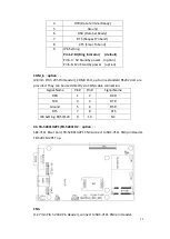
Page 32: ...31 units mm Figure 2 1 Motherboard Dimensions...
Page 83: ...82 Step 3 Read license agreement Click Yes Step 4 Click Next...
Page 84: ...83 Step 5 Click Install Step 6 Click Install...
Page 85: ...84 Step 7 Click Next Step 8 Click Yes I want to restart this computer now Then click Finish...
Page 88: ...87 Step 5 Click Install to begin the installation Step 6 Click Finish to exit the wizard...
Page 92: ...91 Step 3 Read the license agreement Then click Yes to continue Step 4 Click Next to continue...
Page 95: ...94 Step 2 Select Resistive Touch Step 3 Click Next to continue...
Page 97: ...96 Step 6 Wait for installation Then click Next to continue Step 7 Click Continue Anyway...
Page 99: ...98 Step 2 Select Projected Capacitive Step 3 Click Next to continue...
Page 102: ...101 Step 9 Go to C Program Files eGalaxTouch Click Next Step 10 Click Next...
Page 109: ...108 About This panel displays information about the PenMount controller and driver version...
Page 120: ...119 Hardware Saturn Hardware Configuration...
Page 121: ...120 About To display information about eGalaxTouch and its version...

