background image

Packing List


Accessories (as ticked) included in this package are: 


□ 

AC power cable 


□ 

Driver & manual CD disc 


□ 

Other._  

(please specify) 


Safety Precautions


Follow the messages below to avoid your systems from damage: 


◆ 

Avoid your system from static electricity on all occasions. 


◆  Prevent  electric  shock.  Don

t  touch  any  components  of  this  card  when  the  card  is 

power-on. Always disconnect power when the system is not in use. 


◆ 

Disconnect  power  when  you  change  any  hardware  devices.  For  instance,  when  you 

connect  a  jumper  or  install  any  cards,  a  surge  of  power  may  damage  the  electronic 

components or the whole system. 

Summary of Contents for PCH3582

Page 1: ...sPanelPC withAtomD525processor 14628 Central Ave Chino CA 91710 tel 909 597 7588 fax 909 597 1939 Copyright 2013 Acnodes Inc All rights reserved Product description and product specifications are subj...

Page 2: ...lass A computing device pursuant to FCC Rules which are designed to provide reasonable protection against such interference when operated in a commercial environment Operation of this equipment in a r...

Page 3: ...damage Avoid your system from static electricity on all occasions Prevent electric shock Don t touch any components of this card when the card is power on Always disconnect power when the system is no...

Page 4: ...Mainboard Specifications 13 2 2 Jumpers Setting and Connectors 17 Chapter 3 BIOS Setup 3 1 Operations after POST Screen 26 3 2 BIOS SETUP UTILITY 27 3 3 System Overview 28 3 4 Advanced Settings 29 3 5...

Page 5: ...72 5 2 Windows 2000 XP USB Driver Installation 72 Figures Figure 1 1 Dimensions of PCH3582 9 Figure 1 2 Dimensions of PCH3782 10 Figure 1 3 Dimensions of PCH3982 11 Figure 1 4 Overview of PCH3X82 12 F...

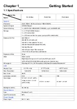
Page 6: ...1XDC Power input T B connector 7 Pin T B for 2in out 1Ground Switch Expansion Slots None OSD OSD control Brightness Screen and Touch on off Power on off APC 3782 3783 3982 3983 add auto tune function...

Page 7: ...ing V E S A 7 5 x 7 5 M o u n t VESA 75x75 Mount VESA 75x75 Mount VESA 100x100 Mount Dimensions WxHxD 3 3 5 W x 2 6 5 H x 6 7 D m m 399 W x324 H x 67 D mm 432 W x358 H x 66 8 D mm 470 W x388 6 H x 67...

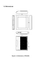
Page 8: ...1 2 Dimensions Figure 1 1 Dimensions of PCH3582...

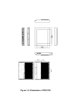
Page 9: ...Figure 1 2 Dimensions of PCH3782...

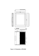
Page 10: ...Figure 1 3 Dimensions of PCH3982...

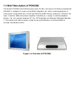
Page 11: ...t comes with a compact flash slot 2 5 inch hard disk drive DDR3 memory audio jack 2 Ethernet DC input 4 external USB ports ensure simplified connectivity to a variety of external peripheral devices Th...

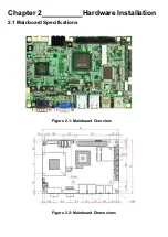
Page 12: ...Chapter 2 Hardware Installation 2 1 Mainboard Specifications Figure 2 1 Mainboard Overview Figure 2 2 Mainboard Dimensions...

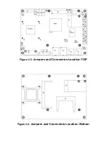
Page 13: ...Figure 2 3 Jumpers and Connectors Location TOP Figure 2 4 Jumpers and Connectors Location Bottom...

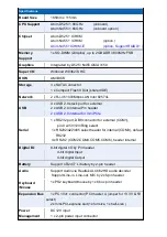
Page 14: ...al Pin header 2 x USB 2 0 internal for mini PCIe 1 x RS232 port DB9 connector for external COM1 pin 9 w 5V 12V Ring select 1 x RS232 422 485 select header for internal COM3 default RS232 4 x RS232 COM...

Page 15: ...re programmable 1 255 second by Super I O 1 x COM Port COM1 4 x USB 2 0 Ports stack 2 x RJ45 GbE Ports 10 100 1000Mbps 1 x DB15 Port or 2x8 Pin Header Operating 20 70 Storage 40 85 Humidity 5 95 non c...

Page 16: ...the POST screen press the F1 or DEL key to enter CMOS Setup Utility to load optimal defaults 5 4 1 5 After the above operations save changes and exit BIOS Setup 2 JVCCIO 2 0mm Pitch 1x3 Pin Header PC...

Page 17: ...owered on or under S0 S1 state the LED is normally on when the system is under S4 S5 state the LED is off Pin5 6 POWER on off Button They are used to connect power switch button The two pins are disco...

Page 18: ...mper pin 1 6 are used to select signal out of pin 9 of COM1 port pin 7 12 are used to select output type for COM3 port RS232 Type or RS422 Type or RS485 Type JCOM Pin Function CLOSE 1 2 COM1 Pin9 RI d...

Page 19: ...ype RS232 Type RS485 Type 12 F_AUDIO 2 0mm Pitch 2x5 Pin Header Front Audio An onboard Realtek ALC662 codec is used to provide high quality audio I O ports Line Out can be connected to a headphone or...

Page 20: ...1 2 5V Default Pin2 3 12V option Note COM3 port is controlled by pins No 7 10 of JCOM For details please refer to description of JCOM and COM33 BIOS Setup 14 KB MS 2 0mm Pitch 1x6 box Pin Header PS 2...

Page 21: ...t hand and right hand side of the Ethernet port indicate the activity and transmission state of LAN 17 VGA CRT Connector DB15 Video Graphic Array Port provide high quality video output They can not wo...

Page 22: ...er supply is DC 12 5 V before power on or it may cause boot up failure and even system damage 22 FAN 2 54mm Pitch 1x3 Pin Header Fan connector cooling fans can be connected directly for use You may se...

Page 23: ...for LVDS1 Pin Signal Name 1 DC12V 2 DC12V 3 Ground 4 Ground 5 BKLT_EN 6 BKLT_CTRL 25 SATA1 2 3 SATA 7P SATA1 SATA2 SATA3 SATA Connectors Three SATA connectors are provided with transfer speed up to 3...

Page 24: ...e screw holes for fixed MPCIE2 assemble 31 MPCIE 50 95x30mm socket 52Pin mini PCIE socket it is located at the bottom it supports mini PCI E devices with USB2 0 SMBUS and PCI E signal 32 CF CF Card so...

Page 25: ...configured CMOS Settings Wrong CMOS Data Time Not Set Press F1 to Run SETUP Press F2 to load default values and continue 0085 After optimizing and exiting CMOS Setup the POST screen displayed for the...

Page 26: ...system summary information will appear BIOS SETUP UTILITY Main Advanced PCIPnP Boot Security Chipset Exit System Overview User ENTER TAB or SHIFT TAB to Select a field Use or to configure system Time...

Page 27: ...l Help F10 Save and Exit ESC Exit AMIBIOS Version 08 00 16 Build Date 03 22 12 ID L706V012 Processor Intel Atom CPU D525 1 80GHz Speed 1800MHz Count 2 System Memory Size 2038MB System Time 00 06 31 Sy...

Page 28: ...Configuration MPS Configuration PCI Express Configuration Smbios Configuration USB Configuration V02 68 Copyright 1985 2009 American Mega trends Inc 3 4 1 CPU Configuration BIOS SETUP UTILITY Main Adv...

Page 29: ...on Enhanced Configure SATA as IDE Primary IDE Master Not Detected Primary IDE Slaver Not Detected Secondary IDE Master Not Detected Secondary IDE Slaver Not Detected Third IDE Master Not Detected Thir...

Page 30: ...Screen Select Item Charge Field F1 General Help F10 Save and Exit ESC Exit Serial Port1 Address 3F8 Serial Port1 IRQ IRQ4 Serial Port2 Address 2F8 Serial Port2 IRQ IRQ3 Serial Port3 Address 3E8 Seria...

Page 31: ...mperature 41 105 CPUFAN Speed 4800 RPM CPUFAN Mode Setting Manual Mode CPUFAN PWM Control 250 V02 68 Copyright 1985 2009 American Mega trends Inc CPU Temperature Show you the current CPU temperature C...

Page 32: ...Not Detected AHCI Port2 Not Detected V02 68 Copyright 1985 2009 American Mega trends Inc While entering setup BIOS auto detects the presence of IDE devices This displays the status of auto detecting o...

Page 33: ...1 4...

Page 34: ...mum Read Request Size Auto Active State Power Management Disabled Extended Synch Auto V02 68 Copyright 1985 2009 American Mega trends Inc Relaxed Ordering Maximum Payload Size Auto Disabled Enable Aut...

Page 35: ...Advanced Smbios Configuration SMBIOS SMI Wrapper Support for PnP Func 50h 54h Select Screen Select Item Charge Field F1 General Help F10 Save and Exit ESC Exit Smbios Smi Support Enabled V02 68 Copyr...

Page 36: ...ces Enabled None Legacy USB Support Enabled USB2 0 Controller Mode Hispeed BIOS EHCI Hand Off Enabled Hotplug USB FDD Support Auto USB Mass Storage Device Configuration V02 68 Copyright 1985 2009 Amer...

Page 37: ...terconnect is a computer bus that allows I O device to operate nearly as fast as CPU in its own way Some technical terms will be mentioned here We recommend that non professional users not make change...

Page 38: ...RQ7 Available IRQ9 Available IRQ10 Available V02 68 Copyright 1985 2009 American Mega trends Inc Clear NVRAM No Yes Plug Play OS No Yes PCI Latency Timer 32 96 64 128 160 192 224 248 Allocate IRQ to P...

Page 39: ...9 10 11 14 15 Available Reserved Available Specified IRQ is available to be used by PCI PnP devices Reserved Specified IRQ is reserved for use by legacy ISA devices DMA Channel 0 1 3 5 6 7 Available...

Page 40: ...Setting Configuration Boot Device Priority V02 68 Copyright 1985 2009 American Mega trends Inc Boot Setting Configuration Quick Boot Enabled Disabled Allows BIOS to skip certain tests while booting Th...

Page 41: ...o Enabled Disabled Wait For F1 If Error Wait for F1 key to be pressed if error occurs Enabled Disabled Hit DEL MessgaeDisplay Displays press DEL to run Setup in POST Enabled Disabled Interrupt 19 Capt...

Page 42: ...n Disabled V02 68 Copyright 1985 2009 American Mega trends Inc Change Supervisor Password Install or Change the password Change User Password Install or Change the password Password Check Setup Always...

Page 43: ...em boot to control unauthorized access to your computer Users may enable the feature in Security Option of Advanced BIOS Features If Security Option is set to System you will be requested to enter the...

Page 44: ...F1 General Help F10 Save and Exit ESC Exit PCI MMIO Allocation 4Gb To 3072MB DRAM Frequency Auto Configure DRAM Timing by SPD Enabled Initate Graphic Adapter IGD Internal Graphics Mode Select Enable 8...

Page 45: ...de DVMT Mode Select Screen Select Item Charge option F1 General Help F10 Save and Exit ESC Exit DVMT Mode Select DVMT Mode DVMT FIXED Memory 256MB Boot Display Device VBIOS Default Flat Panel Type 102...

Page 46: ...Note Panel support PWM Function 3 8 2 South Bridge Configuration Level9 Level0 15 BIOS SETUP UTILITY Chipset North Bridge Chipset Configuration Options Auto Max MHz Select Screen Select Item Charge F...

Page 47: ...DRAM Timing By SPD Enabled Disabled Initate Graphic Adapter Select which graphics controller to use as the primary boot device IGD PCI IGD PCI PEG PEG IGD PCIE PCI Internal Graphics Mode Select Enable...

Page 48: ...anel Type 1024x768LVDS Panel Backlight Control Level 9 HDCP Support Disabled V02 68 Copyright 1985 2009 American Mega trends Inc DVMT Mode Select DVMT Mode FIXED Mode DVMT FIXED Memory Size 256MB 128M...

Page 49: ...t Screen Select Item Enter Go to sub screen F1 General Help F10 Save and Exit ESC Exit Save Changes and Exit Discard Changes and Exit Discard Changes Load Optimal Defaults Load Failsafe Defaults V02 6...

Page 50: ...IO Programming 3 10 1 SuperIO Model Winbond W83627UHG GPIO OUT use GP 60 63 GPIO IN use GP 20 23 3 10 2 W83627UHG Access index port 4Eh 4Fh Index Address Port 4Eh Index Data Port 4Fh 3 10 3 Configure...

Page 51: ...function mode Example x86 assembly code mov dx 4Eh mov al 87h out dx al out dx al Example C code outportb 0x4E 0x87 outportb 0x4E 0x87 Exit the extended function mode Writing AAh to index address port...

Page 52: ...if LDN 9 out dx al Example C code outportb 0x4E 0x30 Logic device activation control outportb 0x4F inportb 0x4F 0x2 Set bit 1 to enable GPIO Port2 if LDN 9 Or outportb 0x4E 0x30 Logic device activati...

Page 53: ...PIO value Example x86 assembly code mov dx 4Eh mov al 0E5h GPIO data reg out dx al mov dx 4Fh in al dx Bit 3 0 GPI 3 0 value Example C code outportb 0x4E 0xE5 GPIO data reg GP inportb 0x4F Bit 3 0 GPI...

Page 54: ...er I O index access port define INDEXP 0x4E define DATAP 0x4F Enter super I O programming mode define ENTERPRG outportb INDEXP 0x87 outportb INDEXP 0x87 Super I O index write define WRITEREG reg val o...

Page 55: ...chip programming EXITPRG return 0 Initialize the GPIO port6 int InitGP6 Start the super I O chip programming ENTERPRG Select the logical device 8 GP6 SELETDEV 8 Activate GP1 WRITEREG 0x30 inportb 0x30...

Page 56: ...cGP2 0xF Exit the super I O chip programming EXITPRG return cGP2 Write GPIO Port6 int WriteGP6 unsigned char cGP6 Start the super I O chip programming ENTERPRG Select the logical device 8 GP6 SELETDEV...

Page 57: ...InitGP6 Read GPIO Port 2 cGP ReadGP2 printf nRead GPIO Port 2 Status X cGP Write GPIO Port 6 WriteGP6 cGP printf nSet GPIO Port 6 Status X cGP return 0...

Page 58: ...therboard The contents include Chipset Atom D525 ICH8M GMA 3150 VGA Chipset Network Adapter Realtek ALC662 HD Audio Driver Touch Panel Driver Installation instructions are given below Important Note A...

Page 59: ...4 1 Chipset Driver To install the chipset driver please follow the steps below Step 1 Access Industrial Panel PC Select Chipset Atom D525 ICH8M Step 2 Click Next to setup program...

Page 60: ...Step 3 Read the license agreement Click Yes to accept the terms of the license agreement Step 4 Click Next to continue...

Page 61: ...Step 5 Click Next Step 6 Select Yes I want to restart this computer now Click Finish then remove any installation media from the drives...

Page 62: ...4 2 GMA 3150 VGA Chipset Driver To install the VGA drivers follow the steps below to proceed with the installation Step 1 Select GMA 3150 VGA Chipset Step 2 Click Next to continue...

Page 63: ...Step 3 Click Next to continue setup program Step 4 Read the license agreement Click Yes to accept the license agreement...

Page 64: ...Step 5 Click Next Step 6 Click Next to continue...

Page 65: ...Step 7 Select Yes I want to restart this computer now Click Finish then remove any installation media from the drivers...

Page 66: ...4 3 Network Adapter Driver To install the Network adapter Driver please follow the steps below Step 1 Select Network Adapter Step 2 Click Next to continue...

Page 67: ...Read license agreement Select I accept the terms in the license agreement then click Next to continue Step 4 Select Drivers PROSet for Windows Device Manager Advanced Network Services Click Next to co...

Page 68: ...Step 5 Click Install to begin the installation Step 6 Click Finish to compete the installation...

Page 69: ...er Installation To install the Realtek High Definition HD Audio driver please follow the steps below Step 1 Select Realtek ALC662 HD Audio Driver from the list Step 2 Wait for extracting the files the...

Page 70: ...Step 3 Click Yes to continue the installation Step 4 Wait for installation...

Page 71: ...Step 5 Select Yes I want to restart my computer now then click OK...

Page 72: ...verter built in to make the total printed circuit board denser circuit diagram also designed for 12 bit ADC for optional There are two connectors on this board one connector is for 4 5 8 wire touch sc...

Page 73: ...se plugged in before the machine is turned on When the system first detects the controller board a screen appears that shows Unknown Device Do not use this hardware wizard Press Cancel Step 2 Insert t...

Page 74: ...Step 4 Read the license Agreement Click I agree to agree the license agreement Step 5 Choose the folder in which to install PenMount Windows Universal Driver Click Install to start the installation...

Page 75: ...Step 6 Wait for installation Then click Next to continue Step 7 Click OK...

Page 76: ...Step 8 Click Finish to compete installation...

Page 77: ...the PenMount Control Panel are Device Multiple Monitors Tools and About which are explained in the following sections Device In this window you can find out that how many devices are detected on your...

Page 78: ...Use command mode call calibration function this can uses Standard 4 9 16 or 25 points to calibrate E g Please run ms dos prompt or command prompt c Program Files PenMount Universa Driver Dmcctrl exe...

Page 79: ...o start calibration procedure NOTE The older the touch screen the more Advanced Mode calibration points you need for an accurate calibration Use a stylus during Advanced Calibration for greater accura...

Page 80: ...nt Control Panel and select Tools then Click Advanced Calibration Step 4 Select Device to calibrate then you can start to do Advanced Calibration NOTE Recommend to use a stylus during Advanced Calibra...

Page 81: ...Setting...

Page 82: ...About This panel displays information about the PenMount controller and driver version...

Page 83: ...COM ports via the RS 232 interface Driver installation procedures are the same as for a single monitor Multiple Monitors supports the following modes Windows Extend Monitor Function Matrox DualHead M...
Page 84: ...rocedure is finished maybe you need to calibrate for each panel and controller NOTES 1 If you used a single VGA output for multiple monitors please do not use the Multiple Monitors function Just follo...

Page 85: ...e touch screen Please press S to skip mapping step Tools Draw Tests or demonstrates the PenMount touch screen operation Advanced Calibration Enable Advanced Calibration function Right Button Icon Enab...

Page 86: ...ontroller that are plugged to your system PenMount Monitor Menu Icon The PenMount monitor icon PM appears in the menu bar of Windows 2000 XP system when you turn on PenMount Monitor in PenMount Utilit...

Page 87: ...isplay Driver Rotate Function nVidia Display Driver Rotate Function SMI Display Driver Rotate Function Intel 845G GE Display Driver Rotate Function Configuring the Rotate Function 1 Install the rotati...

Reviews: