12
necessary to install separate fuses or circuit breakers for supply conductors.
Series AF, AL, BF, AS, AG, IC, GD, GDR, SS, SF, L
Fuse: fuse nominal current of 100 % - 115 % of the pump nominal current.
Characteristics: gG
Circuit breaker: nominal current 100 % - 115 % of the pump nominal current.
Series GF
Input of grinder pump GF is higher then nominal in cutting operation! Current protection setting
value must correspond with this!
Fuse: fuse nominal current of 100 % - 140 % of the pump nominal current.
Characteristics: gG
Circuit breaker: nominal current 100 % - 140 % of the pump nominal current.
5.1.3
El.motor of pump is necessary to protect against short connection and overloading by suitable protecting
device, which in case of defect switch off all phase conductors. Devices protecting from overload according to
CSN EN 60947-4-1 standard or regional standards.
The current setting should be the same as the pump nominal current stated on the label (see 4.1 and 3.0).
Is necessary to observe all aforeside requirements, although in el.motor is installed additional thermal
protection.
Explanation: Additional thermal protection after switch-off can be started in time, when stator (wiring) and
motor frame are not enough cooled-down.
Recomended protection device is for example:
- motor starter
- current relay with contactor
5.1.4
Do not place electric connections under water, as there is a risk of short circuit.
5.1.5
Pump and Float switch cables must be 100% watertight connected in all length to el.switchbox. Otherwise
incorrect evaluation of signals or operation faults may occur.
5.1.6
The pumps must not be used in swimming pools if there are any people in water.
5.1.7
In case of using the pump in swimming pool, outside fountains, garden ponds and similar places the pump
must be powered via a current protector (RCD), the nominal residual operating current shall not exceed 30
mA.
5.2
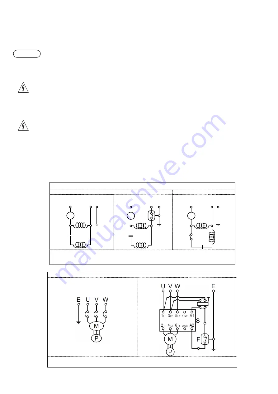
CONNECTING THE PUMP
Single-phase motor
up to 0,75 kW incl.
above 0,75 kW
without float switch
with float switch
without float switch
M-main motor winding, A-auxilliary motor winding, P-thermal protection, F-float switch, S-
centrifugal switch, C-capacitor, E-ground line wire (yellow-green), L-power (phase) line wire
(brown), N-power (zero voltage) line wire (blue)
Three-phase motor with float switch
witout float
with float
P-thermal protection; M-motor winding; T–transformer; S–contactor; F–float switch; E–ground line
wire (yellow-green); U–power line wire (brown); V–power line wire (black); W–power line wire (gray)
C
E
L
N
P
M
A
C
E
L
N
P
M
A
F
S
E
L
N
P
M
A
C
WARNING


