max. 12 cm
Assambly unit
ACO Light Shaft
for Pedestrian
Article No. 35595
plant.
h. Lay the surrounding paving around the
Light Shaft in a mortar bed.
Height adjustment for Light
Shafts 100 x 100 x 40 +
100 x 130 x 40
Prior to backfilling:
1. Loosen screws.
2. Position Light Shaft at the required
height (max. + 12 cm)
3. Retighten the screws.
4. Continue from instruction “f”
Assembly ACO Raising Element
(old model) pedestrian only:
1. Only possible after the Light Shaft has
been assembled.
2. Place the grid in the Raising Element.
3. Position stiffening frame in the Light
Shaft grid seat.
4. Adjust to the desired height by using the
Raising Element. The height can only be
adjusted using the lowest element.
5. Drill the holes.
6. Bolt the Raising Element into position.
7. Backfill carefully in layers with homoge-
neous material, and then compact as
described in instruction “f”.
8. Keep a proper distance away with the
vibrating plate, tamper and heavy plant.
9. Lay the surrounding paving around the
Light Shaft in a mortar bed.
Assembly ACO Raising Element
(old model) light vehicle:
Only possible with 40 cm deep Light
Shaft and with one element. Assemble
directly on cellar wall only. NOT possible
to assemble on insulation. Assemble in
accordance with the assembly instruc-
tions in fixing set Art.-No. 35908.
Assembly of the new ACO
Raising Element
Assemble in accordance with the
assembly instructions in the fixing set.
Important instructions:
• Light Shafts or Raising Elements. Do not
apply loads to Light Shafts or Raising
Elements before they are backfilled.
• Protect Light Shafts from falling objects
during the construction phase.
• During compaction, always place the
grid in position or use the stiffening
frame.
• The compacted soil may settle after
some time.
• Light vehicle Light Shafts should only
be driven over longitudinally (parallel to
the assembly wall). Completely driving
over the Light Shaft only possible in
agreement with the ACO Applications
Engineering Department.
Assembly instructions
Note: These assembly instructions to be read in conjunction with the sales brochure.
ACO Light Shaft
ACO Technologies plc
· Hitchin Road · UK-Shefford · Beds. SG 17 5TE
Tel. 00 44/14 62 81 66 66 · Fax 00 44/14 62 81 58 95 · technologies@aco.co.uk
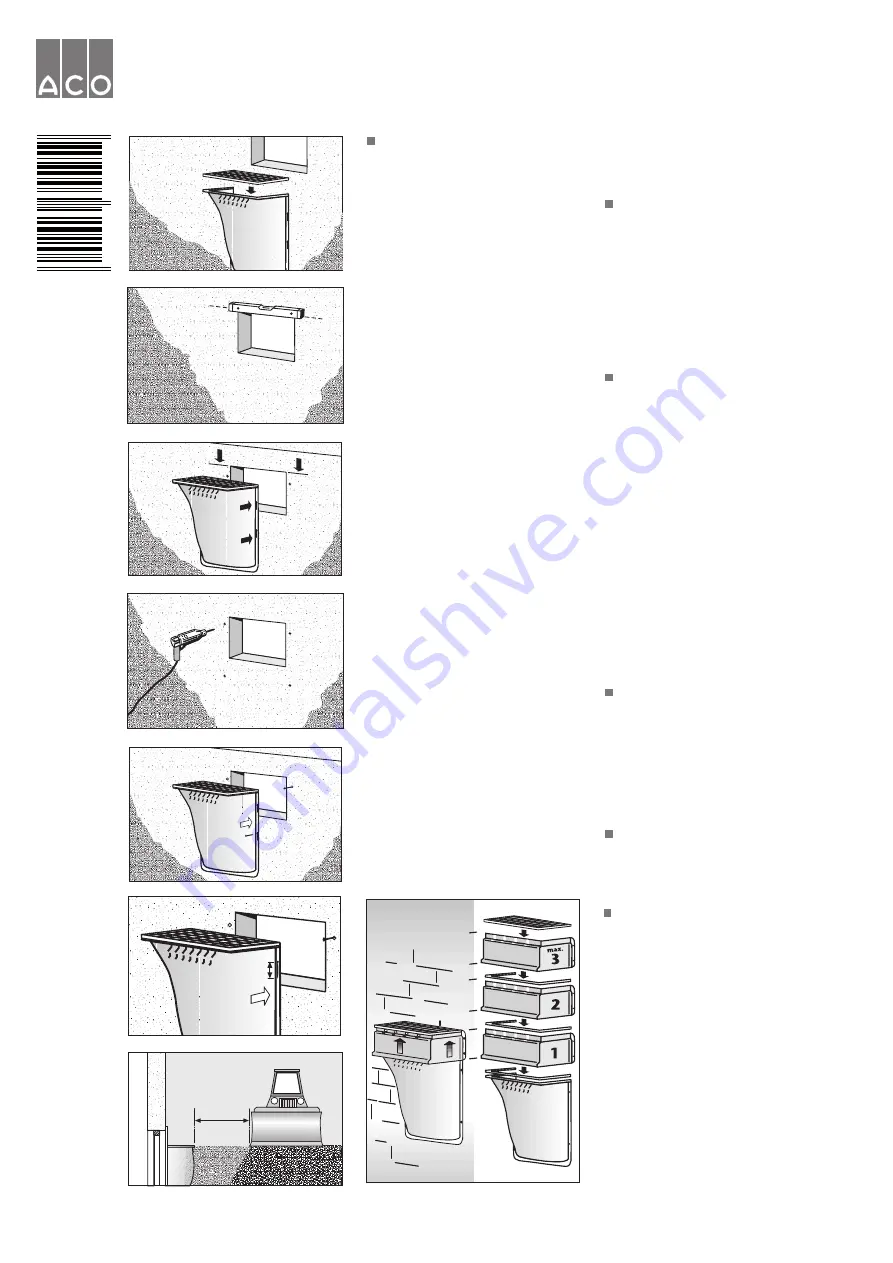
Assembly ACO Light Shaft for
pedestrian/light vehicle (a.-h.)
a. Before securing the Light Shaft in
position, insert the grid and fix the grid
fastener to the Light Shaft.
b. Mark the position of the unit so that the
top edge of the Light Shaft is equal to
the finished surface of the ground level.
When using the ACO assembly aid, the
upper edge of the assembly aid should
equal the top edge of the Light Shaft.
The distance between the lower edge
of the window to the base of the Light
Shaft should be at least 15 cm (pursu-
ant to DIN 18195).
c. Mark the two upper fixing holes with
inserted grid.
d. Drill the holes.
e.
Pedestrian model:
Insert the dowels,
and bolt on the Light Shaft. Use slotted
washers if necessary.
Light vehicle model:
The Light Shaft
must be installed directly on the cellar
wall. Bang in the heavy duty anchors
with the screwed on nuts. Remove the
nuts, hang in the Light Shaft, bolt on
with the washer and the nuts.
Assembly on insulation pedestrian:
Bang in the heavy duty anchors with the
screwed on nuts through the insulation
and into the cellar wall. Remove the
nuts, hang in the Light Shaft, bolt on
with the washer and the nuts. Then drill
the lower holes and fasten the Light
Shaft into position.
f. Backfill carefully in layers with homo-
geneous material, and then compact.
The grid has to be in position during
the compaction process. The distance
between the compactor and the Light
Shaft should become larger as each
higher layer is compacted. The top
layer around the Light Shaft should be
compacted manually. This should be
done in accordance with the regula-
tions in DIN 18300.
g. Keep a proper distance away with
the vibrating plate, tamper and heavy
9-29
37-58
65-86
a.
b.
c.
d.
e.
g.
h.
min. 1 m
40
02626
355959
e.2


