41
7. MAINTENANCE
The user
is not
expected to perform any repairs, except replacing fuses (S.7.2) and
repairing antennas or coaxial cables on the feeders. If needed, call your dealer’s
service provider or the manufacturer directly, see S. 1-2.
7.1 CLEANING
CAUTION
Do not use any solvents for cleaning – solvents may be
dangerous to you and to tuner surfaces.
Do not disassemble the tuner. Cleaning should be performed with a piece of soft cotton
fabric, slightly dampened with water if needed.
7.2 FUSE REPLACEMENT
CAUTION
For replacement, only use standard fuses from the types
recommended below.
There are two fuses in the tuner. They are located under a small cover on the front
panel, Fig. 2-1, ref. (6). The fuses are Euro size (5x20mm), and can have either glass
or ceramic body.
Fuse F1 should be quick blow, fast or flink type (labeled F), rated for 2A and 250V
(Littelfuse: 0235002.MXP, 0235002.HXP, COOPER BUSSMANN BK/GMA-2-R, BK1/
GMA-2-R). It can be ordered from e.g. Digi-Key: F4724-ND, F2680-ND, BK/GMA-2-R,
BK1/GMA-2-R, or from Farnell: 1608243, 1150650.
Fuse F2 should be slow blow, antisurge, tardy or traege type (labeled Т or L), rated for
0.8А and 250V (Bussmann type S504 – 800mA). It can be ordered from e.g. Digi-Key:
BK/S504-800MA-ND, or from Farnell: 534-158.
If any of the two fuses blows, it is most probably the result of too much power applied
(over 60W) during tuning (e.g. due to operator error).
If, after fuse replacement, the device does not operate normally, we recommend repair,
performed by a service technician – call your dealer or the manufacturer directly (See
S. 1-2).
7.3 ACOM 04AT BLOCK DIAGRAM AND PRINCIPLE OF OPERATION
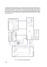
The block diagram can be seen in Fig. 7-1. The ACOM 04AT tuner consists of the fol
-
lowing main assemblies:
-
Input switch board;
Summary of Contents for ACOM 04AT
Page 1: ...1 ...
Page 57: ...2 2 ...

