1mm=39.37mil 1cm=10mm=0.3937” 1m=100cm=3.281ft 1kg=2.205lbs 1m
2
=10.764sq.ft
1km/h=0.62137mph
ACOM LS108
HF Log-periodic Antenna
ASSEMBLING MANUAL
1. GENERAL
INFORMATION
ACOM manufactures a range of antennas designed and produced to give top performance and reliable long-
lasting service. They are completely manufactured of non-corrosive materials. The antennas come partly
factory-assembled in order to facilitate and expedite your labor.
1.1. Introduction and Description
This manual explains the assembling of the ACOM LS108 HF Log-Periodic Antenna. The LS108 is a
directional wideband antenna that covers the HF spectrum between 14 and 30 MHz continuously. It can be
used with the full legal power of 1500W continuously or 3000W PEP.
1.2. Owner Assistance
If assistance or service is needed, your local dealer should be contacted first. In the unlikely event you need
further information, you may get in touch with ACOM by facsimile, telephone, email, or standard mail. Fax:
(+359 2) 920 9656; telephone: (+359 2) 920 9655; e-mail: acom@mail.orbitel.bg; standard mail: ACOM,
Blvd. N. Mushanov 151, 1330 Sofia, Bulgaria.
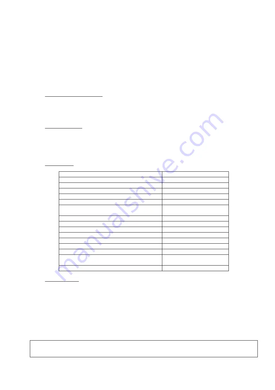
1.3. Specifications
Number of elements
10
Frequency coverage
14-30
М
Hz continuously
Gain (average)
9.5 dBi
Front-to-Back Ratio
20 dB
Nominal Input Impedance
50 Ohm
SWR (typ)
1.5 : 1
Maximum Input Power
1500 W continuously
3000 W PEP
Boom Length
8 m (26.25 ft)
Boom Diameter
50 mm (1.97”)
Mast Diameter
50 mm (1.97”)
Longest Element
11 m (36.1 ft)
Turning Radius
6.8 m (22.3 ft)
Wind-load Area
1.5 m
2
(16,15 sq.ft)
Wind Survival (no ice)
145 km/h (90.0 mph)
Weight
Operating 30 kg (67 lbs)
Shipping 36 kg (80 lbs)
Connectors: antenna / coaxial feed line
SO239A / PL259
1.4. SAFETY FIRST!
Get acquaint with and observe strictly the requirements and instructions of your local legislation. Direct
grounding of the antenna and the tower structure is essential as protection from lightning strikes and static
electricity. The entire earth-connection system must meet your local standard requirements.
Do not install the antenna close to power lines and cables, as their proximity, arc-over or contact with them
during assembly, installation, and exploitation is hazardous and can be lethal.
Do not work alone! You must have at least one assistant always when you work on the antenna. If you have
any doubt concerning the safety, please consult your dealer or engage a professional company.
WARNING!
Exposing to strong electromagnetic radiation can result in dangerous maladies or death. Do not
allow people or animals around the antenna during operation and exploitation.


