ACOM LS108 HF Log-periodic Antenna
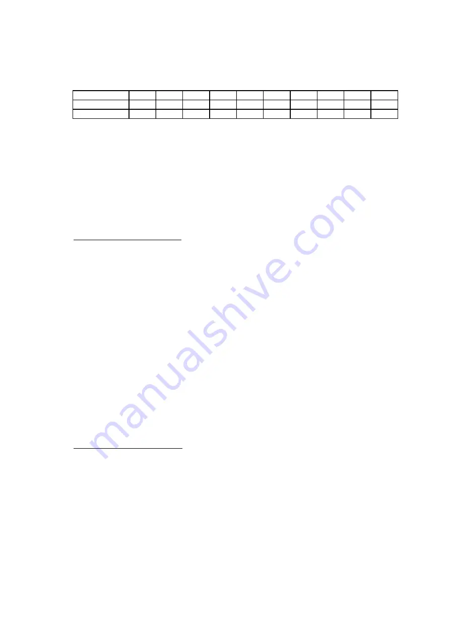
Align the three riveting holes and insert a rivet in each hole, without riveting. Arrange the whole half-element
in this manner for a test only, without riveting for now. Check the total half-element length per
Table 1 - Half-
Element Lengths.
If you find any discrepancy, correct the mistake prior to continuing. This check will ensure
possible mistakes are avoided that could necessitate un-riveting multiple sections at any later stage.
Table 1 - Half-Element Lengths.
Element N
о
.
1
2
3
4
5
6
7
8
9
10
Half-length, m:
5,51
4,98
4,45
3,99
3,57
3,20
2,86
2,56
2,29
2,05
(ft): 18,1
16,3
14,6
13,1
11,7
10,5
9,4
8,4
7,5
6,7
After passing the arrangement test, disassemble the half-element. Lightly smear the contact surface of the
smaller-size section with conductive paste (supplied with antenna). This will ensure corrosion-free electrical
contact between the element sections. Insert the smaller-size section into the next one at a distance of about
100 mm (4”) and align the three riveting holes again. Insert a rivet (4 x 8 mm) in each hole. Begin riveting
them one-by-one, without removing the others out of their places. Support the free rivets in order to keep
them in place during riveting. This is important since the tubes could come out of position otherwise.
Use the "Hand Blind Riveter" tool, which is supplied with antenna, together with the needed number of rivets
(there is a reasonable reserve). Operation instructions about this tool appear on its original packaging.
Proceed similarly to assemble the remaining eighth half-element pairs.
2.3. Mounting the Elements to Boom
All element-supporting insulator blocks are factory mounted on the boom sections. They isolate between
half-elements as well as from each half-element to the boom.
The large ends of the completed half-elements are to be mounted on the supporting insulators at the same
time. All the required hardware and mounting tools are bagged in polyethylene envelopes.
Please look at
Fig. 4 Elements mounting
. Start with the longest element (ELEMENT 1). The left half-
element is marked with “1L” and the right one - with “1R”. The insulator has two channels for element
installation. They have the same marking “1L” and “1R”. Lay the two half-elements in the corresponding
channels.
Select two bolts M5x60 mm and place a plain (flat) washer on each bolt. Align the mount holes of the half-
elements and the insulator. Push the two bolts upside-down through insulator and half-elements. Use the
holes located next to the boom. Please note that the bolts heads are underside of insulator as shown in
Fig.
4 Elements mounting
. Smear a small amount of conductive paste on the tubes as pointed in the figure.
Push an M5x45 mm bolt with a plain washer through the next holes that are more distanced from boom.
Secure with lock washers and nuts on top of the tubes. Tighten the joint well but without deforming the tubes.
Mount the next elements – ELEMENT 2 t
о
ELEMENT 4 on their insulators in the same way.
The rest antenna elements (ELEMENT 5 to ELEMENT 10) should be installed in the same way but you
should use shorter bolts in the holes next to the boom - M5x55 mm. Refer to
Fig. 4 Elements mounting.
2.4. Attachment of Phase-line Straps
The distribution (phase) line feeds each antenna element in the center. It comprises nine pairs of straps
(called phase-line straps hereafter) that cross-connect in pairs between adjacent elements. Each phase-line
strap has a mount hole drilled at each end.
Locate phase-line straps and arrange them in pairs according to length. Now look at
Fig. 5 Phase-line
straps mounting.
Start mounting the longest strap pair between the longest antenna elements (ELEMENT 1
and ELEMENT 2). Place four plain washers on the four bolts of ELEMENT 1 and ELEMENT 2 that are closer
to the boom. Smear these bolts and the strap ends (on the two surfaces) with conductive paste. Attach one
end of the straps on the smeared bolts of ELEMENT 1. Cross the straps above the boom so that their free
ends reach the smeared bolts of the opposite ELEMENT 2. Place a plain washer, lock washer, and a nut on
ELEMENT 1 bolts only.
Do not fully tighten at this time.
The second-length straps should be installed between the inner bolts of ELEMENT 2 and ELEMENT 3 in a
similar way. Remember to smear the straps with conductive paste on the two surfaces. Now place a plain
washer, lock washer, and a nut on the bolts of ELEMENT 2. Do not tighten the nuts yet.
1mm=39.37mil 1cm=10mm=0.3937” 1m=100cm=3.281ft 1kg=2.205lbs 1m =10.764sq.ft
1km/h=0.62137mph
3
2


