background image


www.ACOPower.com

KIT-HYS60MB

4120 Valley Blvd Walnut, CA 91789, USA

+1-626-737 1140

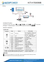
Wiring


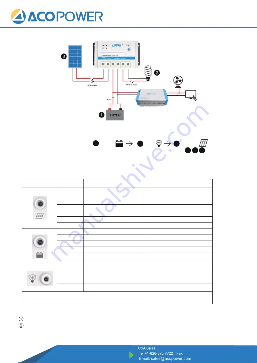
Figure 2 Connection diagram 


Connect  the  system  in  the  order  of 


battery


                    load


PV  array            in accordance 

with Figure 2”Connection diagram” and disconnect the system in the reverse order    


.

1

1

2

2

3

3

Installation Procedure:

Indicators and buttons


(1)Indicator 

Indicator 

Color 

Status 

Information 


Green 

On Solid 

PV  connection  normal  ,but 

low  voltage(low  irradiance) 

from PV, no charging 

Green 

OFF 

No  PV  voltage(night  time) 

or PV connection problem 

Green 

Slowly Flashing(1Hz) 

In charging 

Green 

Fast Flashing(4Hz) 

PV Over voltage 


Green 

On Solid 

Normal 

Green 

Slowly Flashing(1Hz) 

Full 

Green 

Fast Flashing(4Hz) 

Over voltage 

Orange 

On Solid 

Under voltage 

Red 

On Solid 

Over discharged 

Red 

Slowly Flashing(1Hz) 

Battery Overheating 


Red 

On Solid 

Load ON 

Red 

OFF 

Load OFF 

Red 

Slowly Flashing(1Hz) 

Load overload 

Red 

Fast Flashing(4Hz) 

Load short circuit 

Charge, Load and Battery(orange)indicator flashing 

Controller Overheating 

Charge, Load and Battery(red)indicator flashing 

System voltage error 

(2)Button 

The load is turned ON/OFF via the button when the working mode is Manual Control. 

Clear the faults for the load overload and short circuit . 

Summary of Contents for KIT-HYS60MB

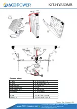
Page 1: ...s 3 Aluminum frame 9a Red Positive Battery Clip 9b Black Negative Battery Clip 10 Anderson Plug 8 Cable 9 Battery Clips 14a Red Positive MC4 Cable 14b Black Negative MC4 Cable 11 Fuse 12 Handy carry b...

Page 2: ...nal solar panel to form a bigger system additional adapter needed please contact us for details After receiving the solar panel kit please check if all accessories are included in the package and prep...

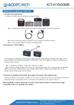
Page 3: ...he charge controller will not power on with a bad battery A good thing to do is to test with your 12 V car battery Step 1 Clamp the red positive battery clip 9a Table1 to the positive terminal of 12V...

Page 4: ...parately 1 Connect the MT 50 to the charge controller with the RS485 cable After an initial welcome screen and device info screen A similar screen will be shown with your own parameters 2 Press ESC to...

Page 5: ...are used as car battery RV battery boat battery and emergency back up battery Step 1 understand your battery battery type capacity and voltage Step 2 check the charge controller s set up We have defa...

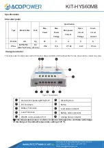
Page 6: ...21 2 lb Charge Controller This solar panel module comes with a 10A solar charge controller which will look like the one shown below colors may vary Figure 1 Characteristic Remote Temperature RTS Port...

Page 7: ...PV connection problem Green Slowly Flashing 1Hz In charging Green Fast Flashing 4Hz PV Over voltage Green On Solid Normal Green Slowly Flashing 1Hz Full Green Fast Flashing 4Hz Over voltage Orange On...

Page 8: ...discharged When the battery voltage is restored to or above LVR low voltage reconnect voltage the load will recover Battery indicator red slowly flashing Battery Overheating The controller will automa...

Page 9: ...Q Is the charge controller waterproof what is IP rate for that A No the charge controller is not waterproof Q Can I use an extension cables in the system A Yes any extension cable with MC4 connectors...

Page 10: ...her types of plugs how do I use this solar panel kit A You will need to refer to the RV user manual and find out what kind of adapter you may need Most adapters are sold on Amazon Please contact suppo...

Page 11: ...months to 18 months Items can be replaced refurbished due to quality issues buyer pays for all shipping Charge Controller The controller itself comes with a 1 year warranty Within 30 days of purchase...

Reviews: