background image

 Chapter3 Installation / 17

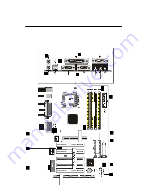
EXTERNAL CONNECTORS

Both Ribbon cable and Connectors on board are with direction signs
to avoid that user insert wrong directions. On other hand, the ribbon
cables should always be connected with the red stripe on the pin 1
of side of the connector.

ISA SLOT1

FAN1

down :

up

K/B

:Mouse

USB

CO M1

C O M 2

Printer

MIDI/

GAME/
AUDIO

FAN2

FA

N

3

JP1

IDE

FD

C

S

O

CKE

T

J3

LA

N

VIA

JP

5

1

IR

J2

12

PC

I1

PC

I2

PC

I3

PC

I5

PC

I4

ISA S

O

LT

AG

P

1

A

G

P SO

L

T

J6

1

JP7

1

1

JP6

DIM

M

FAN 1,2,3
Connector

IR Port

Wake On
LAN

ATX  Power
Connector

Floppy
Driver Connec-
tor

CD Audio
Connector

PS/2 Keyboard

PS/2 Keyboard

PS/2 Keyboard

PS/2 Keyboard

(6-pin Female)

(6-pin Female)

(6-pin Female)

(6-pin Female)

Serial Port(9-pin Male)

Serial Port(9-pin Male)

Serial Port(9-pin Male)

Serial Port(9-pin Male)

COM1

COM1

COM1

COM1

COM2

COM2

COM2

COM2

SPEAKER

SPEAKER

SPEAKER

SPEAKER

MIC

MIC

MIC

MIC

LINE IN

LINE IN

LINE IN

LINE IN

PS/2 Mouse

PS/2 Mouse

PS/2 Mouse

PS/2 Mouse

USB1

USB1

USB1

USB1

USB2

USB2

USB2

USB2

Parallel (Printer) Port

Parallel (Printer) Port

Parallel (Printer) Port

Parallel (Printer) Port

(25-pin Female)

(25-pin Female)

(25-pin Female)

(25-pin Female)

MIDI/(GAME) Port

MIDI/(GAME) Port

MIDI/(GAME) Port

MIDI/(GAME) Port

(15-pin Female)

(15-pin Female)

(15-pin Female)

(15-pin Female)

1

2

3

4

5

6

7

9

10

11

12

13

IDE Connec-
tor

8

 PANEL

Summary of Contents for 6VIA83A

Page 1: ...ce IBM PC AT and PC XT are trademarks of International Busi ness Machines Corporation Pentium is a trademark of Intel Corporation AWARD is a registered trademark of Phoenix Sofftware Inc MS DOS and WINDOWS NT are registered trademarks of Microsoft Corporation Trademarks and or registered trademarks are the properties of their respective owners User s Manual Version 1 0 ...

Page 2: ...tallation Setups 9 Static Electricity Precaution 9 Jumper Settings 10 System Memory DIMM modules 12 DIMM Memory Installation 13 CPU Installation 15 Clearance Requirements 16 Fan Exhaust 16 External Connectors 17 Chapter4 Audio Installation 26 Note If there is any change in the content please refer to our website Regarding the BIOS setting Driver installation refer the web site please www acorp com...

Page 3: ...anized This manual is divided into the following sections Chapter1 Introduction Manual information and checklist Chapter2 Features Information and Specifications con cerning this mainboard Chapter3 Installation Instructions on setting up the board Chapter4 AudioInstallation ...

Page 4: ...that your package is complete If you discover any item damaged or missing please contact with your retailer immediately The 6VIA83 mainboard 1 x IDE UDMA66 ribbon cable 1 x floppy ribbon cable 6VIA83 support software CD driver and utilites This user s Manual ...

Page 5: ...3 is designed for the PC user s who want many new key features processed by the fastest CPU in a economic package This mainboard NewgeneralCPUsupport Socket 370 for Intel PPGA FC PGA PII PIII processor CPU clock select support for 66 100MHz and up to 133MHz CPU bus speed configuration ...

Page 6: ...oller with two connectors that supports four IDE devices in two channels Provides faster data transfer rate and supports Enhanced IDE devices such as Tape Backup and CD ROM devices ATAPI This controller supports PIO mode 3 and 4 16 6MB sec and Ultra DMA 66 66MB Sec also sup ports ZIP100 and LS 120 BIOS support IDE CD ROM or SCSI bootup SuperMulti I O Provides two high speed UART2 compatible serial...

Page 7: ...Support System power up from Modem ring up or timer of System Required enabled in Ring on by modem and Alarm on in BIOS To support CPU FAN On Off and LED indicator under Suspend mode To support CPU temperature detect and Alarm warning by sound option Dimension 30 4 cm x 20 5 cm Supports 16 bits stereo audio controller Sound Blaster 16 PRO compatible with stereo voice up to 48 KHz sampling rates Du...

Page 8: ...e 6VIA83 Mainboard layout ISA SLOT1 FAN1 down up K B Mouse USB COM1 C OM 2 Printer MIDI GAME AUDIO FAN2 FAN3 JP1 IDE FDC SOCKET J3 LAN VIA JP5 1 IR J2 1 2 PCI1 PCI2 PCI3 PCI5 PCI4 ISA SOLT AGP1 AGP SOLT J6 1 JP7 1 1 JP6 DIMM ...

Page 9: ...on 3 Chapter 3 Jumper Jumper Refer to page JP5 Real time Clock RTC clean 11 FAN1 FAN CONN for CPU 19 FAN2 FAN CONN for AGP 19 FAN3 FAN CONN for MB 19 J3 LAN Card Wake Up 24 JP6 JP7 CPU Type Selection 25 J6 JP1 Onboard Sound Function 25 ...

Page 10: ...rs Refer to page KB1 UP PS 2 Mouse port 18 KB1 DP PS 2 Keyboard port 18 USB USB1 2 Port 18 COM1 COM 1 serial port 18 COM2 COM 2 serial port 18 LPT1 Parallel port 18 FDC1 FLOPPY connector 18 IDE1 Primary IDE connector 20 IDE2 Secondary IDE connector 20 IR J1 IrDA connector 21 J5 HDD LED 22 J5 Reset Switch 22 J5 Speaker Connector 23 J5 Power LED 23 J5 ATX Power switch 23 PW1 ATX Power Connector 23 ...

Page 11: ... Static Electricity Precaution Keep the mainboard and other system components in their anti static packaging until you are ready to install them Do all preparative work on a static free surface with the main board components facing up Unplug your computer when working on the inside Wear an Anti static wrist strap Hold the system components boards or cards by its edges only Be careful not to touch ...

Page 12: ...he left when holding the mainboard with the keyboard away from yourself P1 is written besides pin 1 on jumper with three pins The jumpers will also be shown graphically such as to connect pin 1 2 and to connect 2 3 Jumpers with two pins will be shown as for Short on and for Open off For manufac turing simplicity it may be sharing pins from other groups Use the diagrams in this manual instead of fo...

Page 13: ...ta 3 Move the jumper back to Default 4 Turn on your computer 5 Hold down Delete during bootup and enter BIOS setup to re enter user Preferences ISA SLOT1 FAN1 down up K B Mouse USB COM1 COM 2 Printer MIDI GAME AUDIO FAN2 FAN3 JP1 IDE FDC SOCKET J3 LAN VIA JP5 1 IR J2 1 2 PCI1 PCI2 PCI3 PCI5 PCI4 ISA SOLT AGP1 AGP SOLT J6 1 JP7 1 1 JP6 DIMM JP5 CMOS Clear 2 3 default Normal 3 4 Clear CMOS 4 1 4 1 ...

Page 14: ...v SDRAM EDO RAM DIMM 3 16MB 32MB 64MB 128MB 256MB Bank 4 5 168 pin 3 3v SDRAM EDO RAM DIMM 4 16MB 32MB 64MB 128MB 256MB Bank 6 7 168 pin 3 3v SDRAM EDO RAM TotalSystemMemory Max1024MB Note The DIMM Slot does not support any 5v EDO DIMM module The DIMM Slot does not support any 5v SDRAM DIMM module Memory speed setup is required through Auto Con figuration in BIOS chipset Setup of BIOS SOFTWARE If ...

Page 15: ...he orienta tion as shown SDRAM DIMM modules have different pin contacts on each side and therefore have a higher pin density ISA SLOT1 FAN1 down up K B Mouse USB COM1 COM 2 Printer MIDI GAME AUDIO FAN2 FAN3 JP1 IDE FDC SOCKET J3 LAN VIA JP5 1 IR J2 1 2 PCI1 PCI2 PCI3 PCI5 PCI4 ISA SOLT AGP1 AGP SOLT J6 1 JP7 1 1 JP6 DIMM 1 6 8 P i n D I M M S o c k e t 88 pins 60 pins 20 pins ...

Page 16: ...nDRAMDIMMNotchKeyDefinitions The notch on the DIMM module will shift between left center or right to identify the type and also to prevent the wrong type to be inserted into the DIMM slot on the Mainboard You must ask your retailer for Specifications before purchasing Four clock signals are supported on this mainboard RFU Unbuffered Buffered 5 0V Reserved 3 3V DRAM Key Position Voltage Key Positio...

Page 17: ...et and open it by first pulling the lever sideways away from the socket then upwards to a 90 degree right angle In sert the CPU with the correct orientation shown The notched cor ner should point towards the end of the lever Because the CPU has a corner pin for two of the four corners the CPU will only fit in the orientation as shown Notch ISA SLOT1 FAN1 down up K B Mouse USB COM1 C OM 2 Printer M...

Page 18: ...f Core Bus frequency Have the following selection 3x 3 5x 4x 4 5x 5x 5 5x 6x 6 5x 7 0x 7 5x 8 CPU Freqency This item lets you set external clock bus clock The possible settings are 66 100 and 133 MHZ Clearance Requirements To maintain proper airflow once the processor is installed on the mainboard the processor and fan heatsink require certain space clearances The clearance above the processor mus...

Page 19: ...r Connec tor CD Audio Connector PS 2 Keyboard PS 2 Keyboard PS 2 Keyboard PS 2 Keyboard 6 pin Female 6 pin Female 6 pin Female 6 pin Female Serial Port 9 pin Male Serial Port 9 pin Male Serial Port 9 pin Male Serial Port 9 pin Male COM1 COM1 COM1 COM1 COM2 COM2 COM2 COM2 SPEAKER SPEAKER SPEAKER SPEAKER MIC MIC MIC MIC LINE IN LINE IN LINE IN LINE IN PS 2 Mouse PS 2 Mouse PS 2 Mouse PS 2 Mouse USB1...

Page 20: ...g devices or other serial devices See Onboard Serial Port in chipset Feature Setup of the BIOS SOFTWARE NOTE Serial D type 9pin F must be connected to the serial port 4 Parallel Printer port You can enable the parallel port and choose the IRQ through Onboard Parallel Port in Chipset Feature Setup of the BIOS SOFTWARE 5 Universal Serial BUS Ports 1 2 Two USB ports are available for connecting USB d...

Page 21: ...ending on the fan manufacturer the wiring and plug may be different The red wire should be positive while the black should be ground Connect the fan s plug to the board taking into consideration the polarity of this connector NOTE The Rotation signal is to be used only by a specially designed fan with rotation signal WARNING The CPU and or motherboard will overheat if there is no air flowing acros...

Page 22: ...quence SCSI IDE First Boot Sequence in the BIOS Features Setup of the BIOS SOFTWARE Pin 20 is removed to prevent inserting in the wrong orientation when using ribbon cables with pin 20 plugged Tip You may configure two hard disks to be both Masters using one ribbon cable on the primary IDE connector You may install one operating system on an IDE drive and another on a SCSI drive and select right o...

Page 23: ...frared in Chipset Feature Setup to select whether UART2 is directed for use with COM2 or IrDA Use the five pins as shown on the Back View and connect a ribbon cable from the module to the motherboard according to the pin definitions ISA SLOT1 FAN1 down up K B Mouse USB COM1 C OM 2 Printer MIDI GAME AUDIO FAN2 FAN3 JP1 IDE FDC SOCKET J3 LAN VIA JP5 1 IR J2 1 2 PCI1 PCI2 PCI3 PCI5 PCI4 ISA SOLT AGP1...

Page 24: ...ave a switch for the connector you may use the Turbo Switch since it does not have a function SMI is activated when it detects a short to open moment and therefore leaving it shorted will not cause any problems It may require one or two pushes depending on the position of the switch Wake up can be controlled by settings in the BIOS but the keyboard will always allow wake up the SMI lead cannot wak...

Page 25: ... connector connects to a ATX power supply The plug from the power supply will only insert in one orientation because of the different hole sizes Find the proper orientation and push down firmly making sure that the pins are aligned IMPORTANT Make sure that the ATX power supply can take at least 10mAmp load on the 5Volt standby lead 5VSB You may experience difficulty in powering on your system with...

Page 26: ...Pin Description 1 5VSB 2 GND 3 SENSOR P3 P1 Wake On LAN Connector 12 CD Audio Connector CD_IN1 CD_IN2 The 4 pin connectors enable the system to receive the audio output from the CD ROM CD_IN1 Description 1 CD R 2 GND 3 CD L 4 GND CD_IN2 Description 1 CD R 2 GND 3 GND 4 CD L 13 Wake Up On LAN J3 This connector connects LAN cards and a Wake On LAN output When the system is in soft off mode LAN activ...

Page 27: ...z Other settings are for experienced users only ISA SLOT1 FAN1 down up K B Mouse USB COM1 C O M 2 Printer MIDI GAME AUDIO FAN2 FAN3 JP1 IDE FDC SOCKET J3 LAN VIA JP5 1 IR J2 1 2 PCI1 PCI2 PCI3 PCI5 PCI4 ISA SOLT AGP1 AGP SOLT J6 1 JP7 1 1 JP6 DIMM Onboard sound Function JP1 J6 Enabled Colse Disenabled Open Bus_FREQ JP7 JP6 Auto detect 6 6 M H Z test only 66 to 100MHZ Not Conn test only 100 to 133M...

Page 28: ...e advantage of your computer s audio capabilities with all of the controls conveniently in one compact space You can play audio CDs wave files in wav and aud formats and MIDI files in mid and rmi formats With the multisource Audio Mixer you can then record your creations as wave files and edit them with the Audio Recorder ...

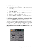
Page 29: ... you to play MIDI files Compact Disk Player enables you to play audio CDs on a CD ROM In addition the AudioRack32 has a miniature mode enabling you to control the AudioRack32 while using minimal screen space The Audio Recorder is a separate application from the AudioRack32 It can be used to add effects and edit files recorded with the Digital Audio Player or by the Audio Recorder itself The Audio ...

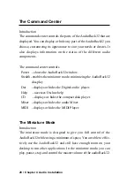
Page 30: ...enables the miniature mode minimizing the AudioRack32 dissplay Dat displays or hides the Digital audio player Help accesses On line help CD displays or hides the compact disk player Mixer displays or hides the audio Mixer MIDI displays or hides the MIDI Player The Miniature Mode Introduction The miniature mode is designed to give you full control of the AudioRack32 while using a minimum of space Y...

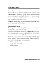
Page 31: ...rols for chorus reverb treble bass and 3 D effects The audio mixer controls The two playback and record toggle buttons are used to switch be tween playback mode and record mode The effects toggle button switches the display to the effects panel where you can use the buttons to enable and disable effects and the sliders to control the amount of the effect There are a number of audio source modules ...

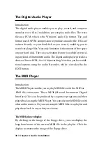
Page 32: ...The digital audio player provides a choice of linear PCM 8 or 16 bit recording Note that you have addi tional options using the audio Recorder which is invoked by the EDIT button The MIDI Player Introduction The MIDI Player enables you to play MIDI files with the MID or RMI file extensions These MIDI Musical Instrument Digital Interface files can be produced by sequencer programs and then played b...

Page 33: ...sis is a lower quality technology compared with Wave table synthesis This card supports Wave table synthesis therefore ESFM is not sup ported on this card The Compact Disk Player Introduction If you have a CD ROM drive you can play audio CDs Check your hardware manual about setting up CD audio hardware and drivers The compact disk player uses intellignet CD playlist management The compact disk pla...

Page 34: ...Audio Recorder can record and play back wav and aud files The Audio Recorder allows a choice of compression from low medium and high ESPCM and ADPCM Release Notes This information is provided for convenience only Information here is subject to change without prior notic View the installation CD for any updated informaation in Readme text files The AudioRack also provides detailed online help click...

Page 35: ...including Line Wave CD Synth Aux A Aux B Mic and Mono In AudioRack can only display six of them at a time You may configure the settings by modifying the file auddrive ini in the Windows directory Under the section MixerRak you can enable or disable the display of each input by setting its corresponding binary value to 1 enable or 0 disable Install Software Wavetable Winnndows 95 98 Insert the Sof...

Page 36: ...er 4 Audio Installation Date Technical Fault Report Motherboard Checked by Serial No Hardware Configuration Used CPU RAM Video Card I O Controller HardDrive Other Card Diagnostic Software Used Fault Description ...

Page 37: ...4 Audio Installation 35 Date Technical Fault Report Motherboard Checked by Serial No Hardware Configuration Used CPU RAM Video Card I O Controller HardDrive Other Card Diagnostic Software Used Fault Description ...

Reviews: